
Production of a custom medical splint or brace for immobilization of a selected region of a patient's body part

Pending Publication Date: 2021-09-30
SWIBRACE SA
View PDF0 Cites 0 Cited by
  • Summary
  • Abstract
  • Description
  • Claims
  • Application Information

AI Technical Summary

Benefits of technology

The patent aims to improve the production of custom splints or braces for immobilizing specific parts of a patient's body. The invention provides a solution that meets this goal and offers benefits in the form of advantageous embodiments.

Problems solved by technology

Situations may however occur where direct moulding of the splint or brace is not possible, for instance in case of a fracture or in case of the presence of cutaneous lesions or wounds in the region to be immobilized.
This approach is likewise not convenient in cases where the patient cannot stand still during moulding of the splint or brace, due e.g. to a neurologic pathology such as Parkinson's disease, or in the event that the patient is simply not physically available for carrying out direct moulding of the splint or brace.
These known solutions have certain limitations and drawbacks, especially in terms of manufacturing costs, robustness, of the resulting custom splints or braces and compliance thereof with medical requirements.

Method used


Image

  • Production of a custom medical splint or brace for immobilization of a selected region of a patient's body part
  • Production of a custom medical splint or brace for immobilization of a selected region of a patient's body part
  • Production of a custom medical splint or brace for immobilization of a selected region of a patient's body part

Examples


Embodiment Construction

[0024]The present invention will be described in relation to various illustrative embodiments. It shall be understood that the scope of the invention encompasses all combinations and sub-combinations of the features of the invention disclosed herein.

[0025]The expression “patient” used herein should be understood as encompassing any human or animal patient. The present invention is therefore applicable to any therapeutic treatment necessitating immobilization of a selected region of a body part of a human or animal.

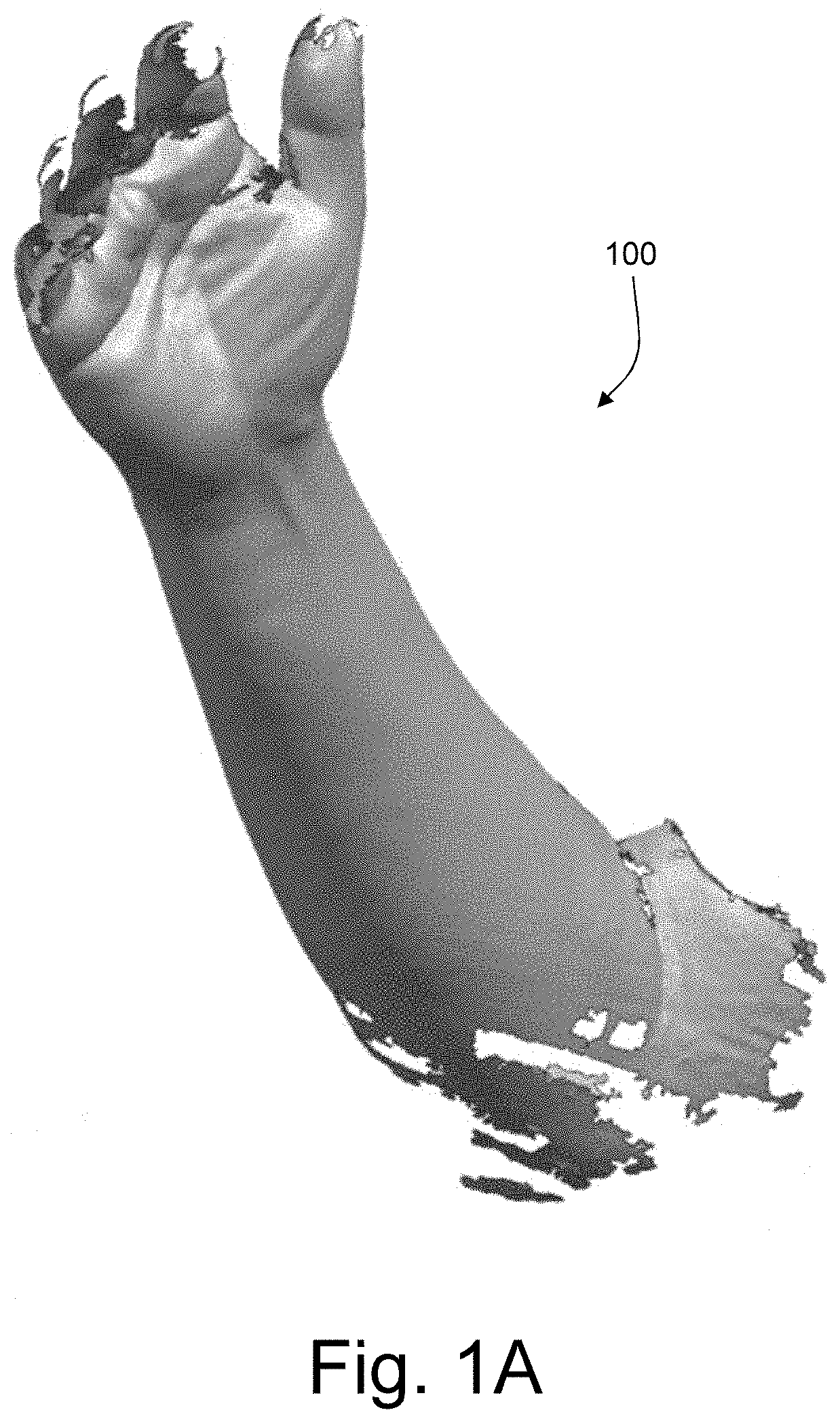
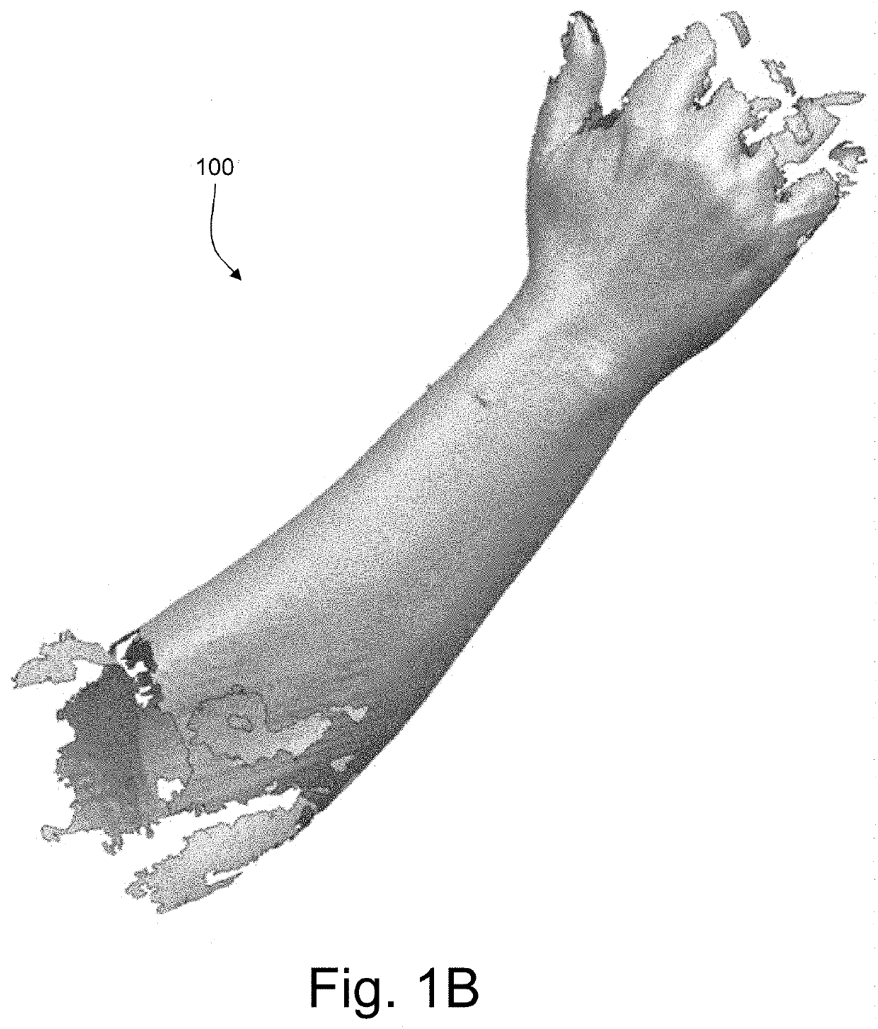
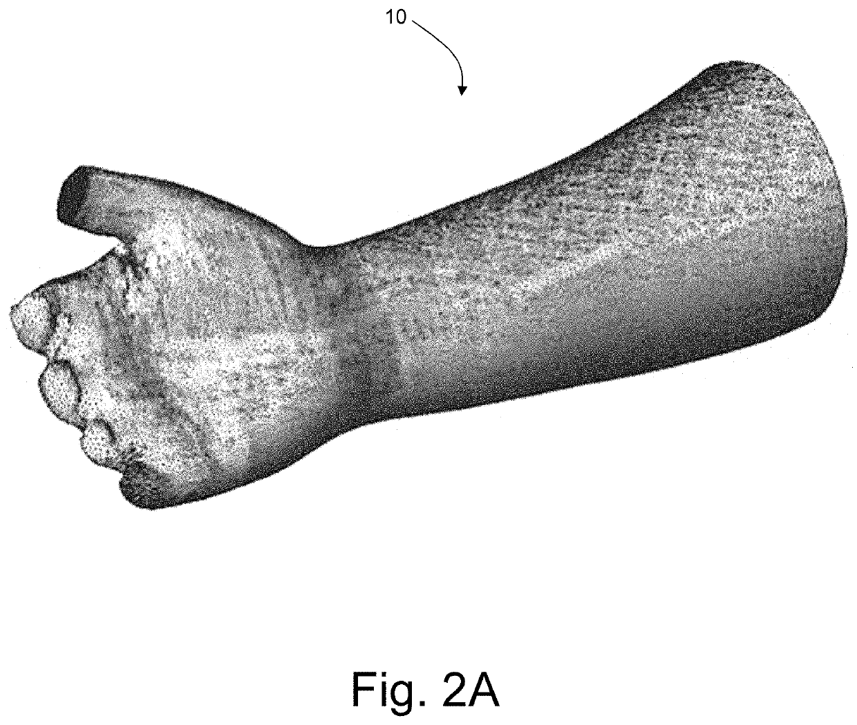
[0026]The invention will be described in the particular context of the production of a custom splint or brace used for immobilization of a human's wrist. An example of such a custom splint or brace, designated by reference numeral 500, is shown in the photographic illustrations of FIGS. 7A and 7B. The custom splint or brace 500 is shown here placed on a selected region A (i.e. the wrist) of the relevant patient's limb L (i.e. the right forearm). It should be appreciated ho...


PUM

PropertyMeasurementUnit
Moldableaaaaaaaaaa
Shapeaaaaaaaaaa
Melting pointaaaaaaaaaa

Abstract

A method of producing a custom medical device including a splint or brace for immobilization of a selected region of a patient's body part. The custom medical device is produced in accordance with the following operations: (a) production of a three-dimensional mold of a portion of the patient's body part including the selected region onto which the desired medical device is to be placed; (b) definition of a three-dimensional shape of the desired medical device covering the selected region; (c) generation of a two-dimensional template corresponding to the defined three-dimensional shape, and which corresponds to unfolding in a two-dimensional plane of the three-dimensional shape of the desired medical device; (d) production of at least one plate of moldable material in accordance with the two-dimensional template of the desired medical device; and (e) molding of the plate of moldable material onto the three-dimensional mold to shape the desired medical device.

Description

TECHNICAL FIELD[0001]The present invention generally relates to the production of a custom medical splint or brace for immobilization of a selected region of a patient's body part, in particular a patient's limb.BACKGROUND OF THE INVENTION[0002]Methods and systems of producing custom splints or braces for immobilization of selected regions of body parts are known as such in the art.[0003]International (PCT) Publication No. WO 2016 / 101331 A1 for instance discloses devices and methods for fabricating a custom splint for use in an immobilization system. One method disclosed in this publication comprises identifying a region of interest of a limb around which a splint is to be positioned, placing markers about the region of interest on the limb, and scanning the region of interest having the markers to generate data for the splint to be produced. In this particular context, photo-polymeric material is positioned around the region of interest and an image of a splint generated from the s...

Claims


Application Information

Patent Timeline
IPC IPC(8): A61F5/01A61F5/058B29C51/36B29C33/38B29C33/40
CPCA61F5/0118A61F5/05866B33Y80/00B29C33/3842B29C33/40B29C51/36A61F2/30942A61F5/05825B29C51/00B29C51/421B29K2875/00B29L2031/753
Inventor SCHUIND, FRÉDÉRIC
Owner SWIBRACE SA
Learn More