Device configured for mounting to a surface

Pending Publication Date: 2022-06-16
AXIS
View PDF2 Cites 0 Cited by
  • Summary
  • Abstract
  • Description
  • Claims
  • Application Information

AI Technical Summary

Benefits of technology

[0005]In view of that stated above, providing a device, preferably a camera device, that improves o

Problems solved by technology

This can in some applications be complicated by that many camera devices are provided with hidden fasteners for attaching it to the wall/ceiling, which may be desirable for an aesthetic perspective an

Method used


Image

  • Device configured for mounting to a surface
  • Device configured for mounting to a surface
  • Device configured for mounting to a surface

Examples


Example

[0027]The present teachings will now be set forth more fully hereinafter with reference to the accompanying drawings, in which currently preferred embodiments of the invention are shown. The teachings may, however, be embodied in many different forms and should not be construed as limited to the embodiments set forth herein; rather, these embodiments are provided for thoroughness and completeness, and fully convey the scope of the claims to the skilled person.

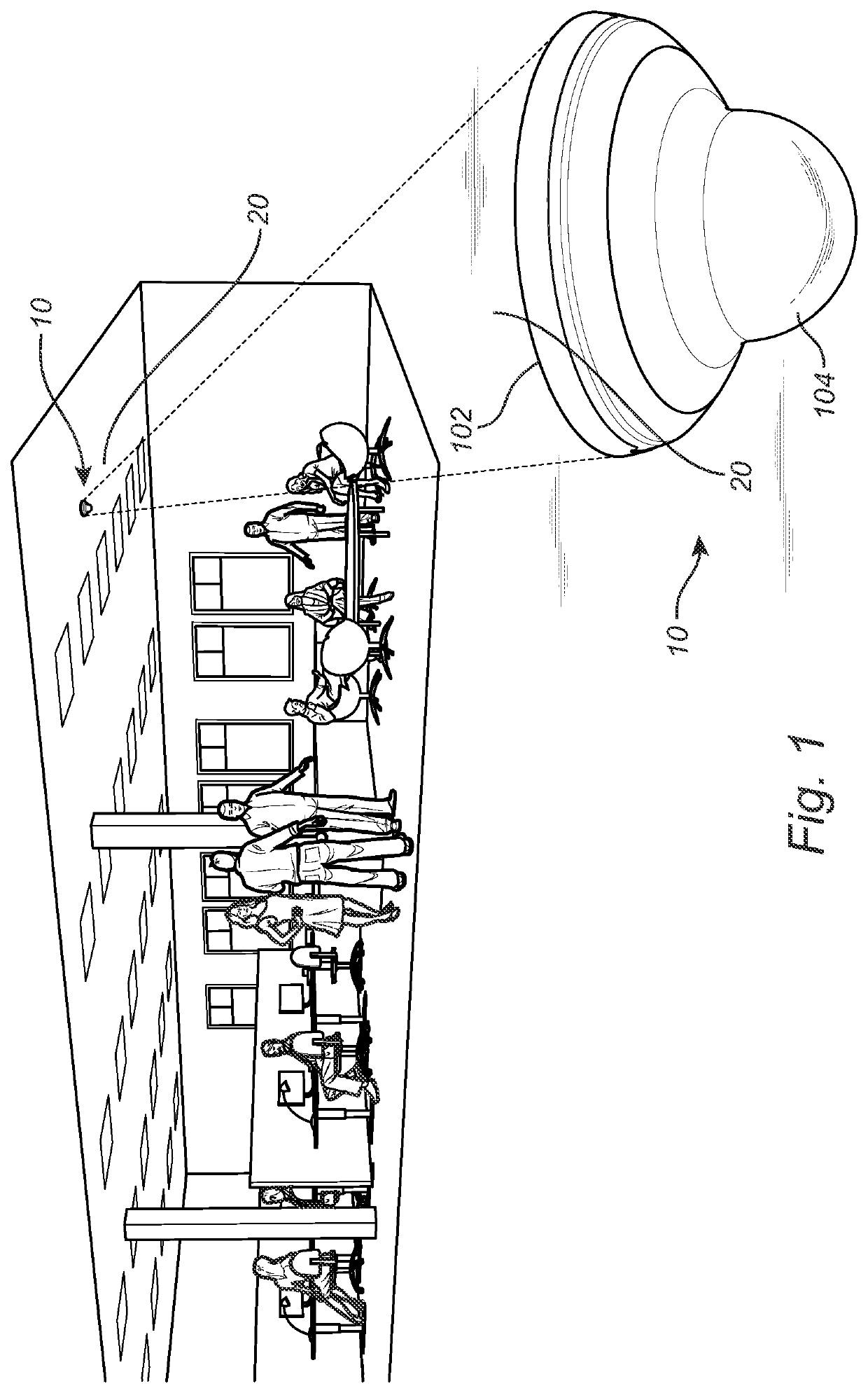
[0028]FIG. 1 discloses a perspective view of a device 10, preferably a camera device 10, which is mounted to a surface 20. The camera device 10 is illustrated as a dome camera but may be embodied as another type of camera suitable for mounting to a surface 20.

[0029]The surface 20 may be any type of surface that is suited for attachment of the camera device 10, such as a wall or a ceiling. Typically, in case the device 10 is a camera device, the device 10 is preferably mounted at an elevated position in relation to its surroundi...


PUM


Abstract

A device configured for mounting to a surface, comprises a base part and an attachment part, the attachment part being attachable to the base part, wherein the base part is provided with a keyhole-shaped opening for receiving a fastener comprising a head and a shaft for attaching the base part to the surface, the keyhole-shaped opening comprises a first segment permitting passage of the head and shaft and a second segment permitting passage of the shaft but preventing passage of the head.

Description

FIELD OF THE INVENTION[0001]The present invention relates to improvements in safety for securing devices such as a camera to a wall and / or to a ceiling, more specifically to a device configured for mounting to a surface.TECHNICAL BACKGROUND[0002]Camera devices which are intended for surveillance and for monitoring of different environments are becoming more and more common. An example of such a camera device is a dome camera, which comprises a semi-spherical camera housing for allowing camera movements in relation to a base which in turn is attached to a support such as a wall or a ceiling. Such a camera allows rotation and tiling in many directions and thus achieves a large field of view. The entire housing may be rotated with the camera following the movements of the housing, or by rotating / tilting a camera mounted inside of the housing while the housing itself is stationary.[0003]To achieve a good vantage point for the camera device and an undisturbed view of its surroundings, th...

Claims


Application Information

Patent Timeline
IPC IPC(8): G03B17/56F16M13/02
CPCG03B17/561F16M13/027F16M13/02G08B13/19632G03B17/56G03B17/02H04N23/51
Inventor PERSSON, MIKAELWIDERDAL, JOHANDITTLÉN, JOHANCOLLINS, LEIGHLUNDBERG, ULF
Owner AXIS
Why Eureka
Try Eureka