
Energy-storage integrated application device and operation thereof

Active Publication Date: 2020-11-19
SIGNIFY HLDG BV
View PDF0 Cites 0 Cited by
  • Summary
  • Abstract
  • Description
  • Claims
  • Application Information

AI Technical Summary

Benefits of technology

The present invention aims to provide an improved solution for communication and power transmission in an application system, especially in a lighting system, while keeping the complexity of the system low. The invention provides an application device with a current controller and communication module that can connect and disconnect from the distribution line based on different modes. The current controller can control power sources and can also control the communication module based on its state and the operation status of the application device. By disconnecting the current controller and communication module during data communication mode, noise from the power source is prevented from interfering with the data communication. Additionally, the application controller can switch from a second mode to a first mode upon receiving a signal indicating that the energy storage of the application device has fallen below a predetermined threshold to avoid power outages. Overall, the invention improves the efficiency and reliability of power and communication in an application system.

Problems solved by technology

In order to implement such communication, additional infrastructure is needed which results in higher cost and a higher complexity of the system.
However, in power line communication systems, each device needs dedicated PLC chipsets to transmit and receive data on a power line.
The power line is prone to noise due to changes in load patterns or switching on the energy distribution grid.
This results in data corruption due to noise in the power system and complex circuitry is needed at both transmitter and receiver end, which again results in increased costs and complexity of the system.

Method used


Image

  • Energy-storage integrated application device and operation thereof
  • Energy-storage integrated application device and operation thereof
  • Energy-storage integrated application device and operation thereof

Examples


Embodiment Construction

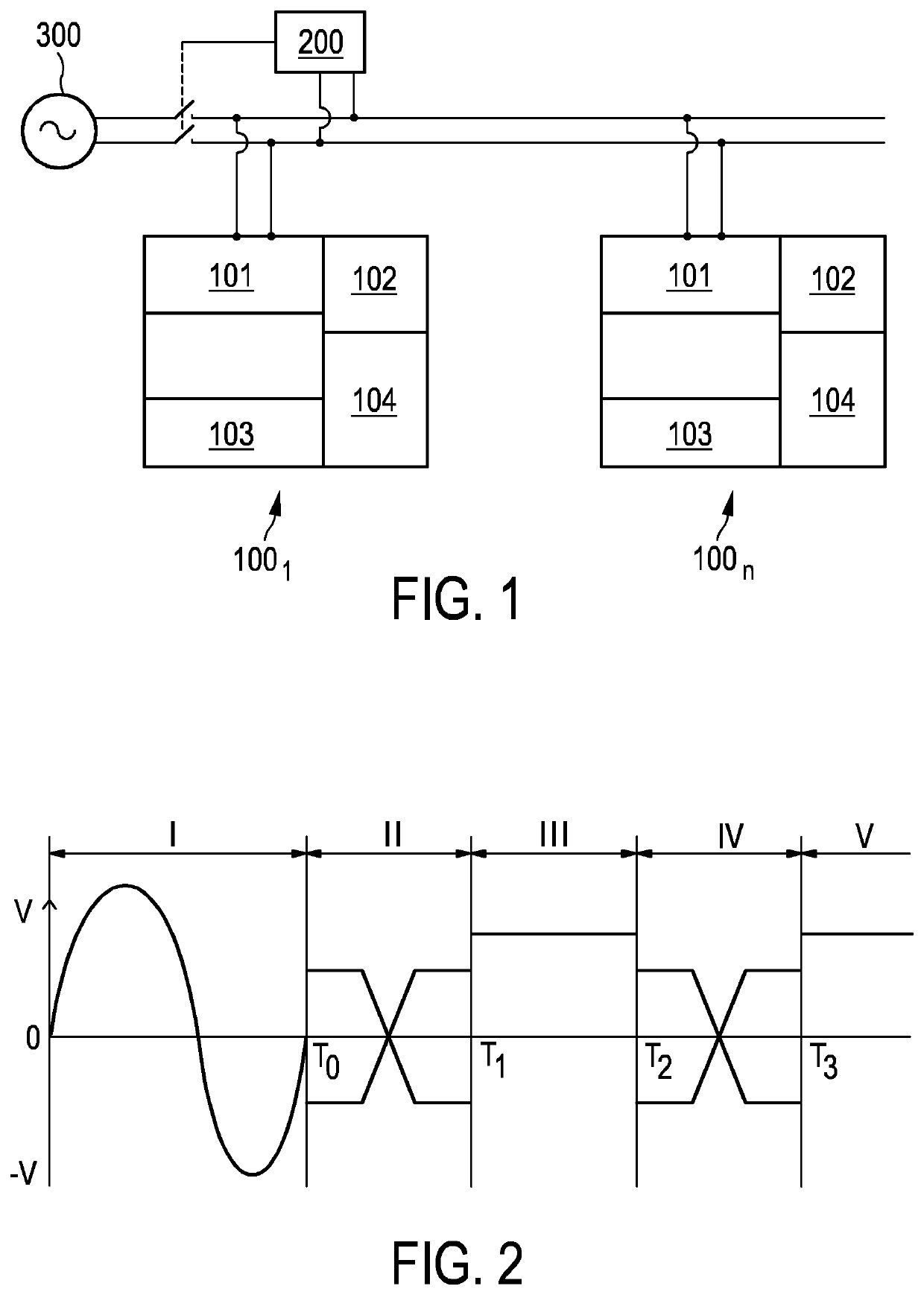
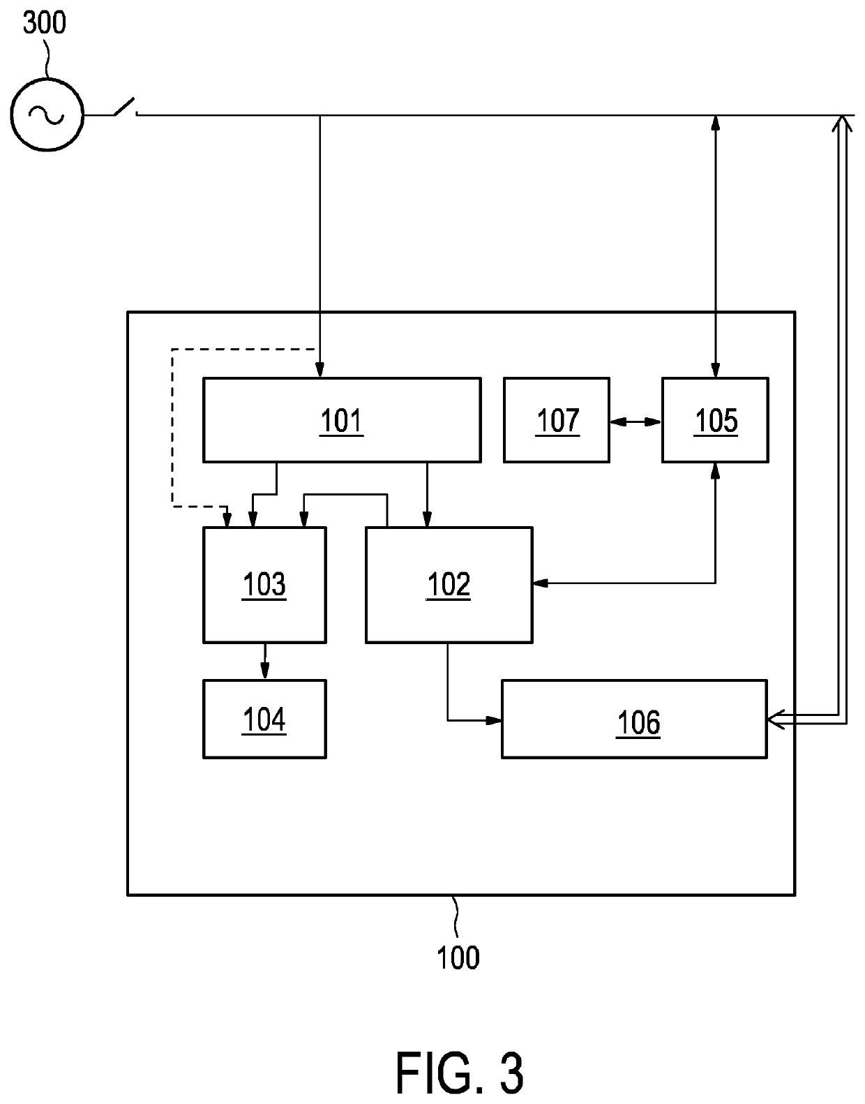
[0030]FIG. 1 exemplary and schematically shows an application system for communication and power transfer between a central application controller 200 and application devices 1001 to 100n with integrated energy storage 102, in particular lighting devices, such as luminaires, lamps, sensors, user interfaces. Further examples of application device 1001 to 100n are any devices exploited in modern building management systems, e.g. heating, ventilation and air conditioning (HVAC) applications.

[0031]The transmission of data communication or AC power via the same distribution line occurs sequentially one after another, such that there is no noise from AC power transmissions during data communication. Accordingly, there is no need for complex circuitry or protocols to extract the information from data embedded in power transmissions. Depending on the power consumption of the application device, the energy storage 102 may be a normal capacitor (e.g. for a user interface), a super capacitor (...


PUM


Abstract

The present invention relates to an application device comprising an integrated energy storage, an application controller and a method of operating an application system, supporting different operation modes. In a first operation mode, AC power is provided via a distribution line to operate the application device. In a second mode, the AC power transmission at the distribution line is replaced by data communication, wherein the application device is run by energy from the energy storage during the second operation mode. Preferably in a third operation mode, DC power from the energy storage of an application device may be provided via the distribution line to another application device.

Description

FIELD OF THE INVENTION[0001]The present invention relates to smart application systems, in particular lighting systems, used in building / household management systems. More particularly, the present invention relates to an application device and application controller operable in different modes to support the exchange of power and communication signals.BACKGROUND OF THE INVENTION[0002]Lighting appliances are growing from just passive devices for fixed constant power illumination to interactive devices. They become smart devices actively participating in creating customized ambience or contributing to energy management in building management systems. The smart operations require communication among lighting devices as well as with a central control, which may be realized by wired or wireless communication, such as e.g. zigbee, wifi, dali or Ethernet. In order to implement such communication, additional infrastructure is needed which results in higher cost and a higher complexity of t...

Claims


Application Information

Patent Timeline
IPC IPC(8): H02J5/00H02J7/00H05B47/185H04B3/54
CPCH04B3/548H02J5/00H02J7/00032H05B47/185H02J7/0047H04B3/54H05B47/22Y02B20/40
Inventor MISHRA, PRIYA RANJANWENDT, MATTHIASRADERMACHER, HARALD JOSEF GÜNTHER
Owner SIGNIFY HLDG BV
Learn More