
Wireless communication system, base-station and user-side-device

Active Publication Date: 2020-06-18
FRAUNHOFER GESELLSCHAFT ZUR FOERDERUNG DER ANGEWANDTEN FORSCHUNG EV
View PDF0 Cites 13 Cited by
  • Summary
  • Abstract
  • Description
  • Claims
  • Application Information

AI Technical Summary

Benefits of technology

The patent describes a way to send data over a network using a combination of amplification and forwarding. This method allows users to send data to and from each other, either in both directions or just one direction. The system makes sure that users' devices are synchronized correctly with the network resources so that the data can be amplified and forwarded correctly. This method improves the quality of service by reducing congestion and avoiding collisions.

Problems solved by technology

The delay over satellite links (earth hub station containing a base-station—satellite—user-equipment) has a strongly variable delay in case of non-geostationary satellites.
A first problem occurs, when satellite links are included in the transmission chain.
So using existing methods from LTE to adjust continuously the TA is not sufficient and would cause significant signaling overhead in the network only for the purpose of timing adjustments.
A second problem is that the delay variation over the satellite link is much more than a Transmission Time Interval (TTI; in LTE: 1 ms) and to be expected to be even less for New Radio, where higher numerologies are considered.
A third problem is the handover from one satellite to another satellite.
For a handover between satellites (from satellite A to satellite B), there is an additional challenge, that all user-equipments within the satellites coverage area experience a strong signal jump (waveform frame structure timing like frame start change, Doppler shift and Doppler spread will change, etc.).
Such a handover can potentially cause network congestion, when all user-equipments will try to perform the initial access / re-access at a time.
In this case, the drifting delay of the link from base-station over satellite to relay-user-equipment complicates the relay functionality, because the frame timing between relay-user-equipment and other user-equipment is drifting.

Method used


Image

  • Wireless communication system, base-station and user-side-device
  • Wireless communication system, base-station and user-side-device
  • Wireless communication system, base-station and user-side-device

Examples


Embodiment Construction

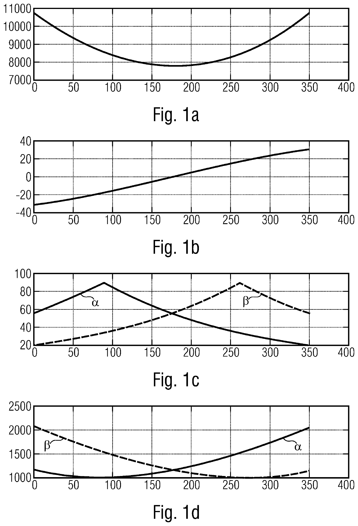
[0152]FIG. 1 shows the effect on the delay due to a satellite link within a wireless communication system.

[0153]FIG. 1a) gives the single hop delay in [s] over time [s]. The orbit height of the satellite is 1000 km.

[0154]FIG. 1b) shows the drift of overall delay with the differential time delay [μ / s] on the y-axis and the time [s] on the x-axis.

[0155]The satellite elevation is shown in FIG. 1c): The elevation [º] is given by the y-axis and time [s] on the x-axis. The first graph (labelled α) refers to the connection between the base-station and the satellite and the second graph (labelled β) refers to the connection between the satellite and the user-equipment.

[0156]The individual distances between base-station and satellite (curve labeled α) and between satellite and user-equipment (curve labelled β) are shown in FIG. 1d). The distances on the y-axis are given in km.

[0157]FIG. 1 illustrates a variable one way delay over the link from base-station (also called hub station) over a lo...


PUM


Abstract

A wireless communication system has at least one user-side-device and a base-station. The at least one user-side-device and the base-station are configured to communicate with each other via a satellite applying a timing-advance-value (TA) for synchronizing an uplink of the communication. The base-station is configured to provide the at least one user-side-device with a satellite-connecting-signal concerning an uplink towards the satellite, the satellite-connecting-signal providing configuration information in order to establish and adjust the uplink to the satellite. The at least one user-side-device is configured to perform an adjustment of the timing-advance-value for a pre-compensation of at least one synchronization offset of an uplink in case the at least one user-side-device receives the satellite-connecting-signal, the satellite-connecting-signal including a granting-signal indicating the user-side-device the allowance to adjust the timing-advance-value. Responsive to the granting-signal, the at least one user-side-device is configured to automatically adjust the timing-advance-value for an unlimited time or for a certain period of time, until the at least one user-side-device receives a new TA adjustment configuration.

Description

CROSS-REFERENCES TO RELATED APPLICATIONS[0001]This application is a continuation of copending International Application No. PCT / EP2018 / 072577, filed Aug. 21, 2018, which is incorporated herein by reference in its entirety, and additionally claims priority from European Application No. EP 17187318.5, filed Aug. 22, 2017, which is incorporated herein by reference in its entirety.[0002]The invention refers to a wireless communication system. Further, the invention refers to a base-station and to a user-side-device. The invention also refers to a method for handling wireless communication between a user-side-device and a base-station via a satellite.BACKGROUND OF THE INVENTION[0003]The delay over satellite links (earth hub station containing a base-station—satellite—user-equipment) has a strongly variable delay in case of non-geostationary satellites. The user-equipment (also named mobile terminal or user terminal) may be on ground (continental or on ships) or located on aerial platform...

Claims


Application Information

Patent Timeline
IPC IPC(8): H04W56/00H04B7/185
CPCH04B7/18508H04W56/0005H04B7/18541H04W56/0045H04B7/2125
Inventor HEYN, THOMASDATTA, ROHITROHDE, CHRISTIANROTH-MANDUTZ, ELKE
Owner FRAUNHOFER GESELLSCHAFT ZUR FOERDERUNG DER ANGEWANDTEN FORSCHUNG EV
Learn More