
Automatic center frequency tuning of a voltage controlled oscillator

Active Publication Date: 2006-05-02
ADVANCED MICRO DEVICES INC
View PDF5 Cites 13 Cited by
  • Summary
  • Abstract
  • Description
  • Claims
  • Application Information

AI Technical Summary

Benefits of technology

[0009]A frequency synthesizer is disclosed that is usable in a wireless communication device and has a phase locked loop, which may reduce phase noise and other signal disturbances and which may provide a radio communication architecture having low complexity and high performance.

Problems solved by technology

However, the performance of the communication system is critically dependent on the purity of the synthesized high frequency output signals.
For signal reception, impure frequency sources result in mixing of undesired channels into the desired channel signal.
For signal transmission, impure frequency sources create interference in neighboring channels.
The level of spectral purity required in cellular telephone applications make the design of a PLL synthesizer solution and in particular, the design of a VCO within a PLL synthesizer solution quite demanding.
Phase noise is undesired energy spread continuously in the vicinity of the output frequency, invariably possessing a higher power density at frequencies closer to the fundamental of the output frequency.
Phase noise is often the most damaging of the three to the spectral purity of the output frequency.

Method used


Image

  • Automatic center frequency tuning of a voltage controlled oscillator
  • Automatic center frequency tuning of a voltage controlled oscillator
  • Automatic center frequency tuning of a voltage controlled oscillator

Examples


Embodiment Construction

[0023]The illustrated embodiments of the present invention will be described with reference to the figure drawings, wherein like elements and structures are indicated by a like reference numbers.

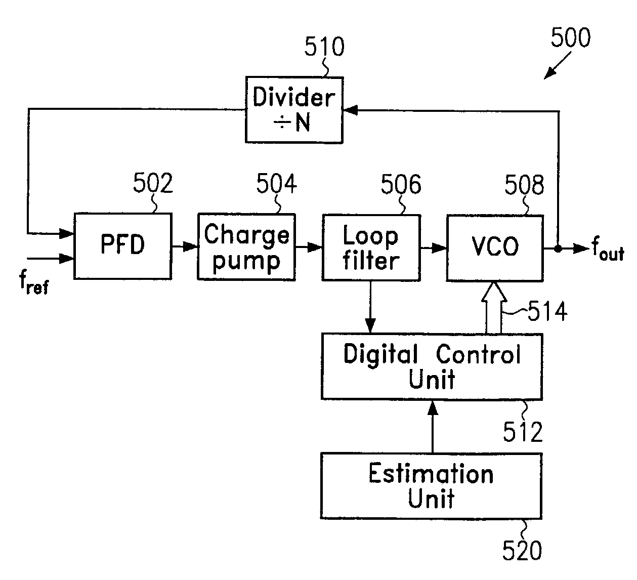
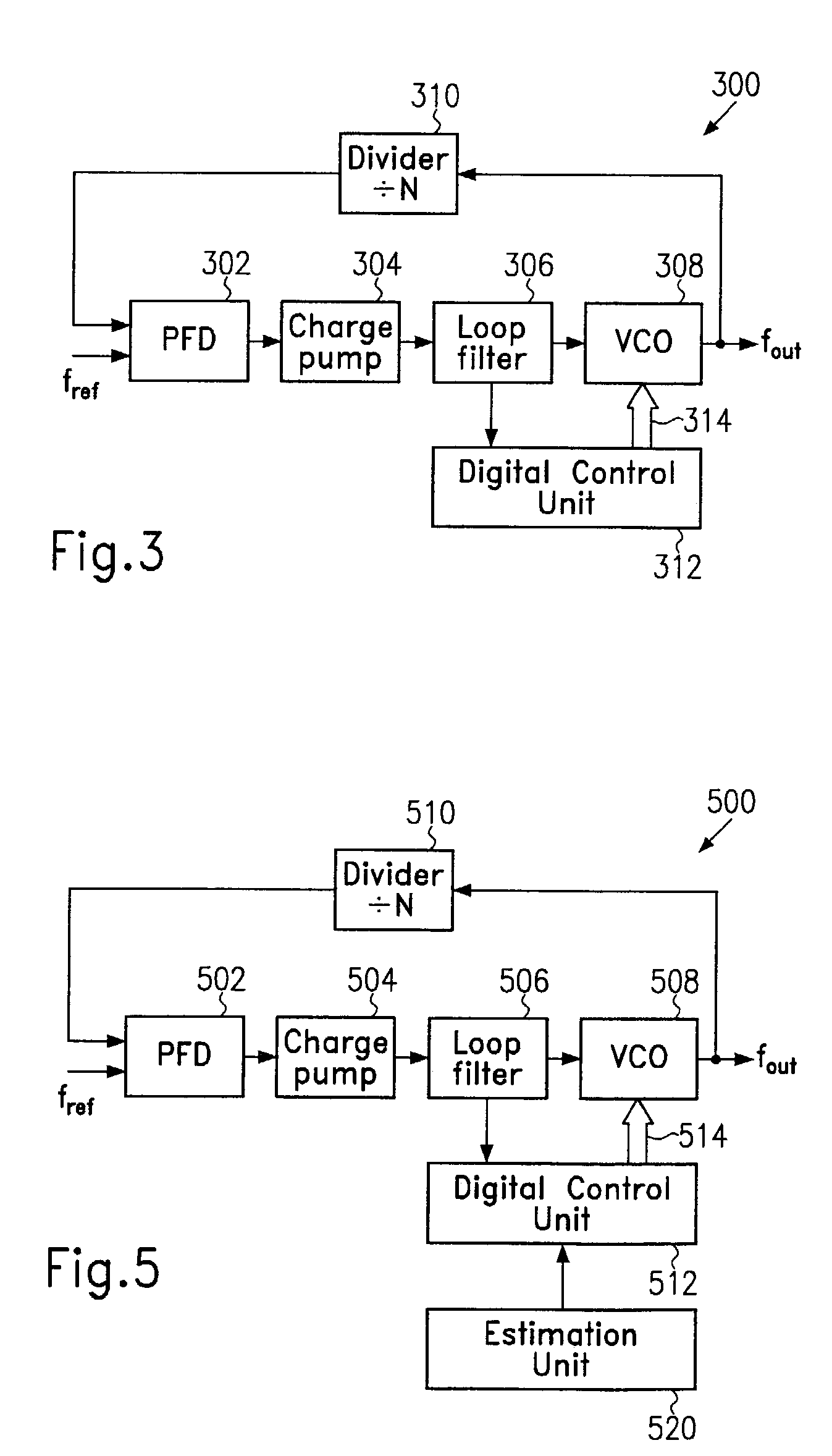
[0024]Referring now to the drawings and in particular to FIG. 3, which is a block diagram of a frequency synthesizer usable in a wireless communication device according to one embodiment, the frequency synthesizer has a phase locked loop 300 comprising a voltage control oscillator 308 for generating an output signal having an output frequency fout. The output signal is frequency divided by means of a divider 310, which may be an integer N divider. This frequency divided signal is compared to a reference signal having a reference frequency fref by means of a phase / frequency detector 302. The phase / frequency detector 302 outputs an error signal, which may be a charge up or charge down and is input to a charge pump 304. The charge pump 304 converts the charge up and charge down signals into a c...


PUM


Abstract

A frequency synthesizer usable in a wireless communication device is disclosed that may ensure a low phase noise and an improved performance. The frequency synthesizer has a phase locked loop comprising a controllable oscillator generating an output signal with an output frequency that can be adjusted within a predefined frequency range dependent on the value of a first control signal. A phase / frequency detector generates an error signal in response to a phase and / or frequency difference between an input signal generated by frequency dividing said output signal, and a reference signal. A loop filter generates the first control signal based on said error signal and outputs same to the controllable oscillator. A control unit generates a second control signal from the loop filter signal and provides the second control signal to the controllable oscillator, which is arranged for modifying the predefined frequency range based on the second control signal.

Description

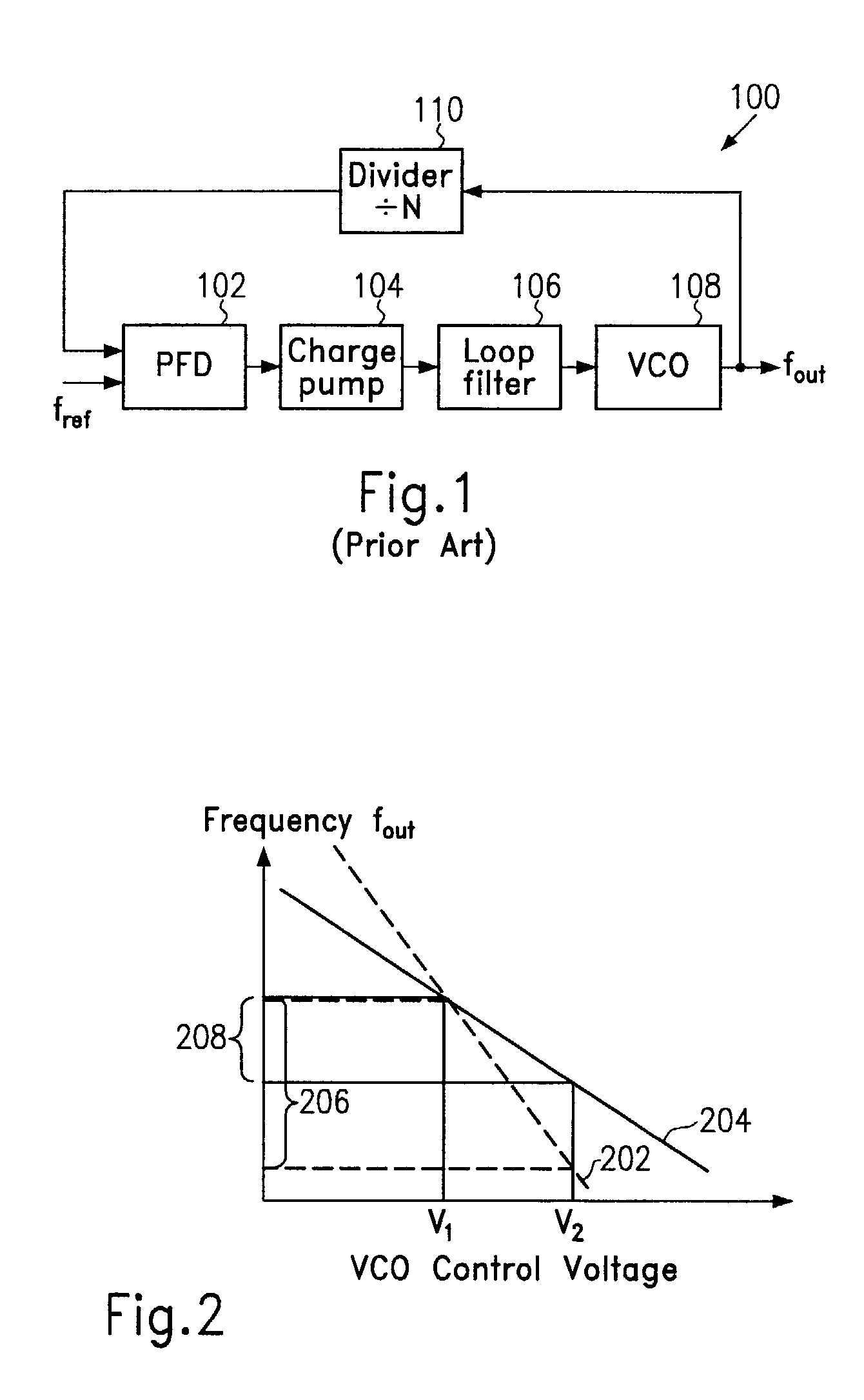
BACKGROUND OF THE INVENTION[0001]1. Field of the Invention[0002]The present invention relates generally to the synthesis of high frequency signals. More particularly, the present invention relates to the synthesis of high frequency local oscillator signals for wireless communication applications.[0003]2. Description of the Related Art[0004]Wireless communication systems typically require frequency synthesis in both the received path circuitry and the transmit path circuitry. Phase locked loop (PLL) circuits including voltage control oscillators (VCO) are of use in mobile unit applications to produce a desired output frequency fout. As depicted in FIG. 1, a typical PLL circuitry 100 uses a phase / frequency detector 102 for detecting a frequency and / or phase difference between a reference frequency fref and the divided output frequency to drive a charge pump 104. This charge pump 104 delivers packets of charge proportional to the phase difference and / or frequency difference to a loop f...

Claims


Application Information

Patent Timeline
IPC IPC(8): H04B1/06H04B7/00H03L7/099H03L7/10H03L7/18H04B1/16
CPCH03L7/099H03L7/18H03L7/10H03L7/103
Inventor JAHENE, ROLFKLUGE, WOLFRAMDRESCHER, HENRY
Owner ADVANCED MICRO DEVICES INC
Learn More