Digital cueing receiver

Active Publication Date: 2006-11-14
AIR FORCE THE UNITED STATES AS REPRESENTED BY THE SEC OF THE
View PDF9 Cites 12 Cited by
  • Summary
  • Abstract
  • Description
  • Claims
  • Application Information

AI Technical Summary

Benefits of technology

[0003]The present invention provides a simple low cost and l

Problems solved by technology

Heretofore such cueing receivers have been realized in analog signal processing form and have thus encounter

Method used


Image

  • Digital cueing receiver
  • Digital cueing receiver
  • Digital cueing receiver

Examples


Example

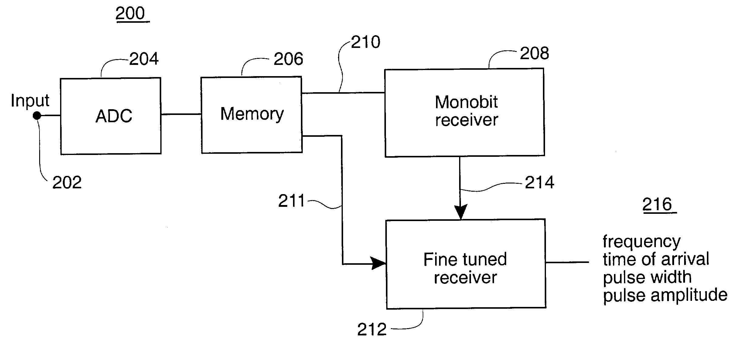
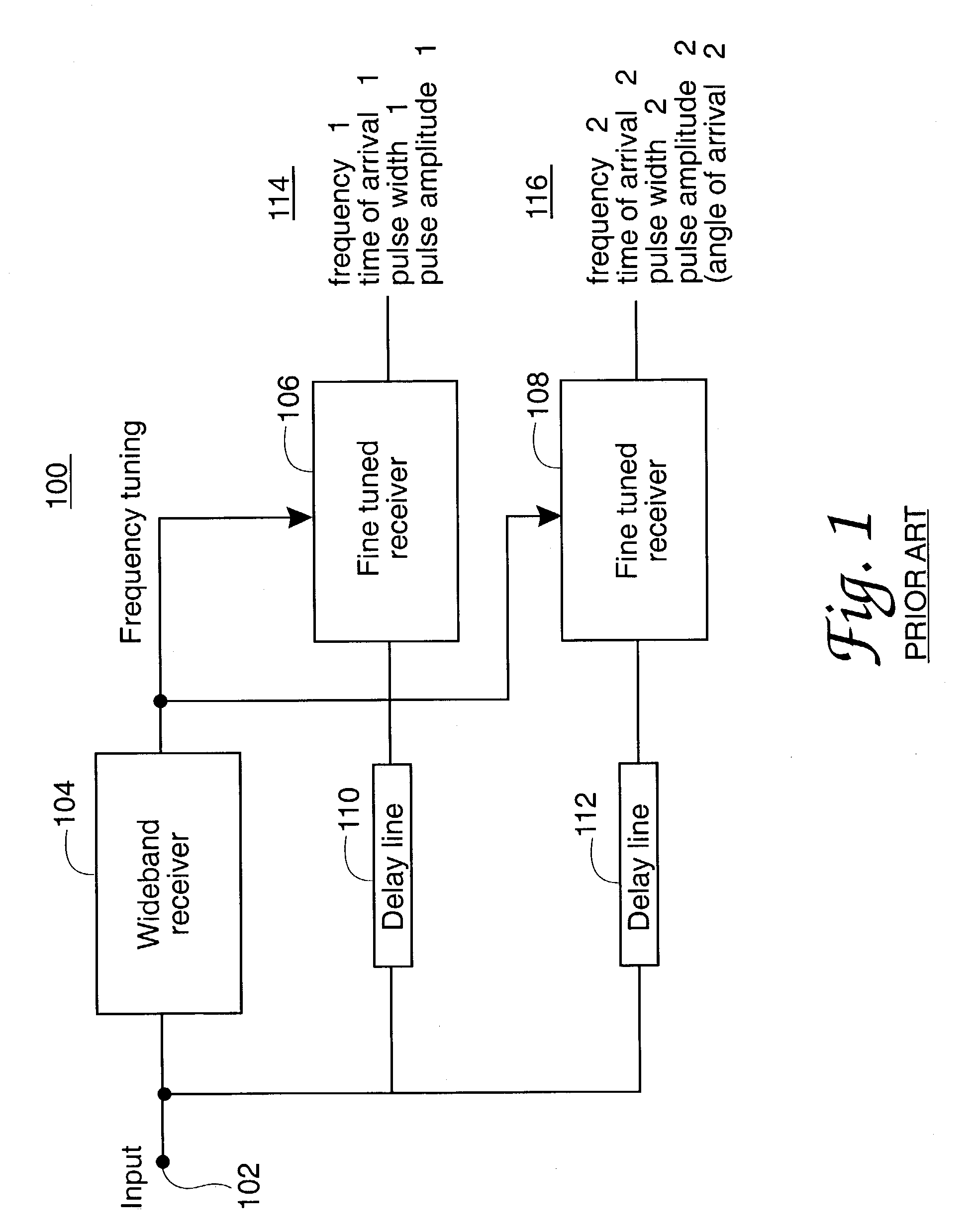
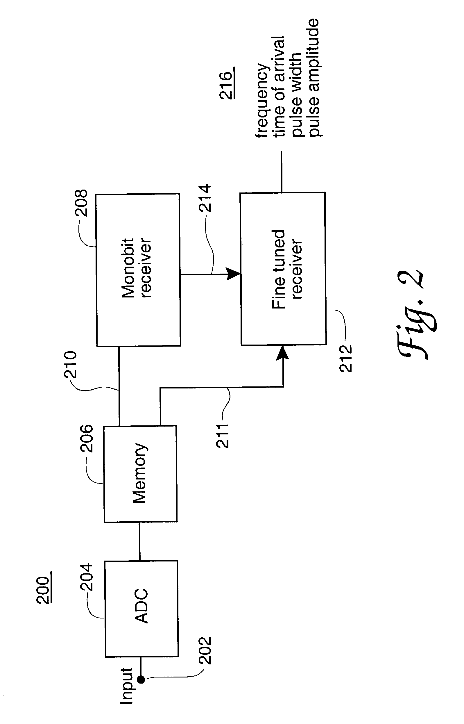
[0022]FIG. 1 in the drawings shows the general principles of a present-day analog cueing receiver system 100. In the FIG. 1 apparatus input signals located within a wide band portion of the electromagnetic spectrum, usually at microwave frequencies, arrive at the node 102 from a receiving antenna and are applied to the input port of a wideband receiver circuit 104 and also propagated toward two narrowband receiver circuits 106 and 108. The input signals at 102 are first processed by the receiver circuit 104, which may be of the channelized receiver type or be another type of receiver having a wide instantaneous bandwidth capability and the ability to identify the frequency of each of multiple input signal component.

[0023]The frequency information determined by the wideband receiver circuit 104 is used to tune one or more fine-tuned receiver circuits such as those shown at 106 and 108 in order to obtain more detailed additional information about the individual input signal(s) receive...


PUM


Abstract

A digital cueing radio receiver system embodied using digital memory in lieu of analog delay lines and thereby avoiding delay line implementation difficulties. The cueing receiver system includes a wideband receiver portion providing an output signal employed for tuning a narrowband receiver portion of the system. Signal delay enabling use of the wideband receiver portion output signals for tuning the narrow band receiver portion selection frequency is provided by a digital memory circuit operating on analog-to-digital converted samples of input signal data of the receiver system. Approximated unity value related mathematical multiplication free Kernel function values are employed in the Fourier transformation. Avoidance of analog delay line-elements in embodying the system is a significant practical advantage of the invention.

Description

RIGHTS OF THE GOVERNMENT[0001]The invention described herein may be manufactured and used by or for the Government of the United States for all governmental purposes without the payment of any royalty.BACKGROUND OF THE INVENTION[0002]Cueing radio receiver receivers are used to control the frequency selection in a second radio receiver in a number of electronic applications, including military electronic warfare systems. As shown in certain of the prior patents identified in connection with the present document, these uses also include signal recorders, signal analyzers and signal processing systems of plural types. Heretofore such cueing receivers have been realized in analog signal processing form and have thus encountered implementation difficulty, size, cost and complexity sufficient to suggest sparing use of such receivers. Additional background information regarding the cueing receiver and its applications may be found in a textbook authored by one of the inventors named in the...

Claims


Application Information

Patent Timeline
IPC IPC(8): G01S7/40
CPCG01S7/021
Inventor TSUI, JAMES B. Y.HARY, STEPHEN L.LIN, DAVID M.
Owner AIR FORCE THE UNITED STATES AS REPRESENTED BY THE SEC OF THE
Why Eureka
Try Eureka