Method and modulation control device for wireless data transmission

Active Publication Date: 2005-09-22
ATMEL CORP
View PDF24 Cites 13 Cited by
  • Summary
  • Abstract
  • Description
  • Claims
  • Application Information

AI Technical Summary

Benefits of technology

[0018] It is therefore an object of the present invention to provide a method for wireless data transmission of the initially mentioned type which improves the

Problems solved by technology

If the coding or a change in the modulation state in the transponder takes place approximately simultaneously with the synchronization markers transmitted by the base station, there exists the danger that the generation or transmission of the synchronization markers will make it more difficult to evaluate the simultaneously backscattered signals, which have a very low power.
When su

Method used


Image

  • Method and modulation control device for wireless data transmission
  • Method and modulation control device for wireless data transmission
  • Method and modulation control device for wireless data transmission

Examples


Example

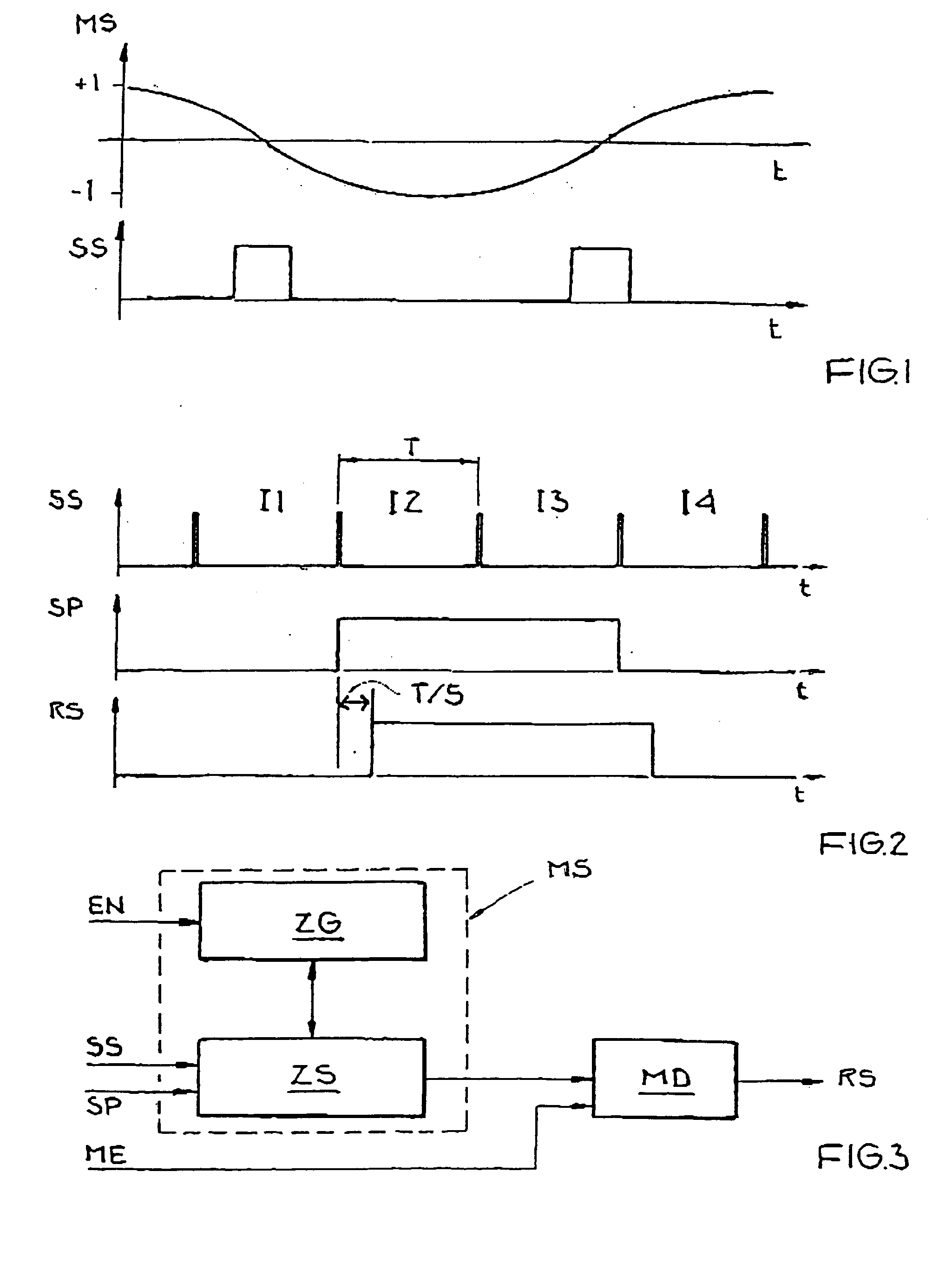
[0031]FIG. 1 shows a diagram of a modulation signal MS of a base station for double sideband modulation with a suppressed carrier. The modulation signal MS is used to modulate a carrier signal (not shown) that is emitted by the base station. FIG. 1 also shows a resulting synchronization marker signal SS generated in an RSSI circuit of a passive transponder. The cosine-shaped modulation signal MS shown in the upper part of FIG. 1 changes the phase position of the carrier signal by 180° upon a transition from +1 to −1 or from −1 to +1.

[0032] The lower part of FIG. 1 shows the resulting synchronization marker signal SS in a transponder on reception of the carrier signal modulated with the modulation signal MS shown above. In the region of the phase transition, the power of the carrier signal drops or briefly goes to zero, which is detected by the RSSI circuit of the transponder. The result is a rectangular shape for the synchronization marker signal SS in the region of the phase trans...


PUM


Abstract

A method and device for wireless data transmission between a base station and one or more transponders, in which electromagnetic carrier waves are emitted by the base station and symbols are transmitted from a given transponder to the base station by modulation and backscattering of the electromagnetic carrier waves, wherein a change in a modulation state takes place synchronously with synchronization markers transmitted by the base station. A change in the modulation state is carried out by a transponder with a specifiable time delay that is relative to the synchronization markers.

Description

[0001] This nonprovisional application claims priority under 35 U.S.C. § 119(a) on German Patent Application No. 102004013885, which was filed in Germany on Mar. 16, 2004, and which is herein incorporated by reference. BACKGROUND OF THE INVENTION [0002] 1. Field of the Invention [0003] The present invention relates to a method for wireless data transmission between a base station and one or more transponders and also a modulation control device for carrying out the method. [0004] 2. Description of the Background Art [0005] Such transmission methods between one or more base stations or readers and one or more transponders are used, for example, in contactless identification systems or so-called radio frequency identification (RFID) systems. Sensors, for example, for temperature measurement, may also be integrated in the transponders. Such transponders are also referred to as remote sensors. [0006] The transponders and their transmitting and receiving devices customarily do not have a...

Claims


Application Information

Patent Timeline
IPC IPC(8): G06K7/00G06K7/10G08C17/02H04J3/06H04L7/00H04L27/00H04L27/02H04Q7/38
CPCG06K7/0008H04L27/00G06K7/10039
Inventor FRIEDRICH, ULRICH
Owner ATMEL CORP
Why Eureka
Try Eureka