Supercharge Your Innovation With Domain-Expert AI Agents!

Spray nozzle

a spray nozzle and spray nozzle technology, applied in the direction of spraying apparatus, liquid spraying apparatus, etc., can solve the problems of reducing overspraying, nozzles typically have no directional control, etc., and achieve the effect of high flow ra

Active Publication Date: 2021-09-30
MEDMIX SWITZERLAND AG
View PDF2 Cites 0 Cited by
  • Summary
  • Abstract
  • Description
  • Claims
  • Application Information

AI Technical Summary

Benefits of technology

This patent aims to create a spray nozzle that can spray at high flow rates with reduced overspray (the amount of material that doesn't reach the desired spray target). This is especially useful for spray targets with a large surface area. The goal is also to create a spray nozzle that is easy and cost-effective to manufacture.

Problems solved by technology

Prior art spray nozzles typically have no form of directional control and hence cannot reduce an overspraying.

Method used


Image

  • Spray nozzle
  • Spray nozzle
  • Spray nozzle

Examples


Embodiment Construction

[0036]Selected embodiments will now be explained with reference to the drawings. It will be apparent to those skilled in the art from this disclosure that the following descriptions of the embodiments are provided for illustration only and not for the purpose of limiting the invention as defined by the appended claims and their equivalents.

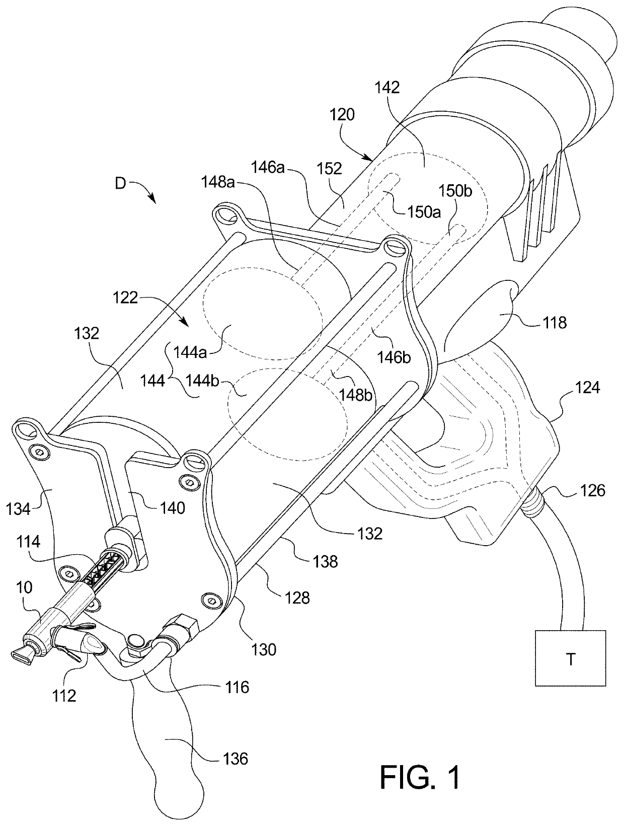
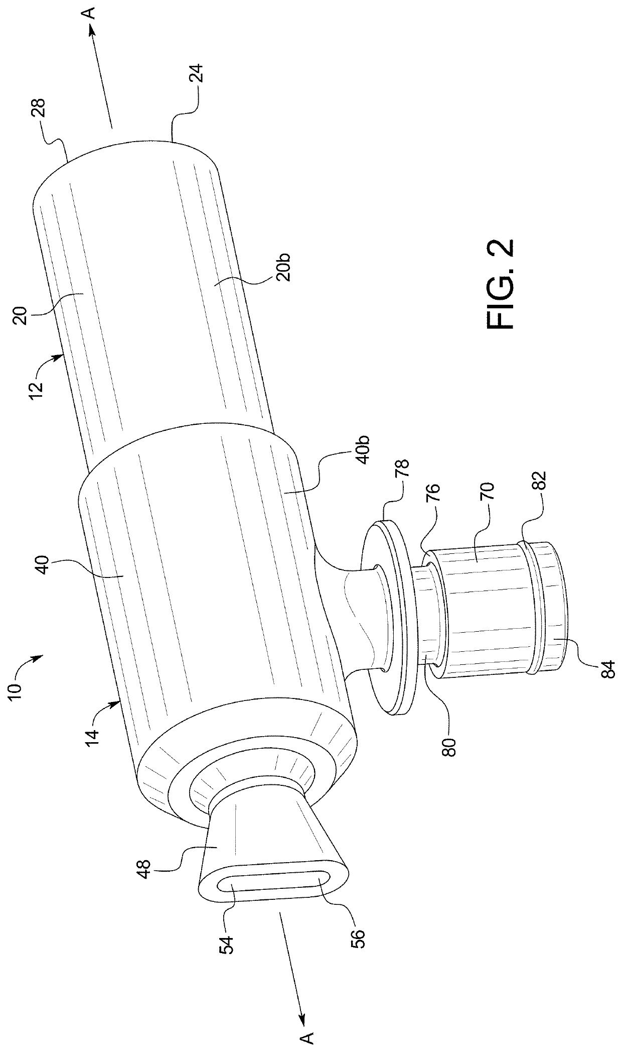
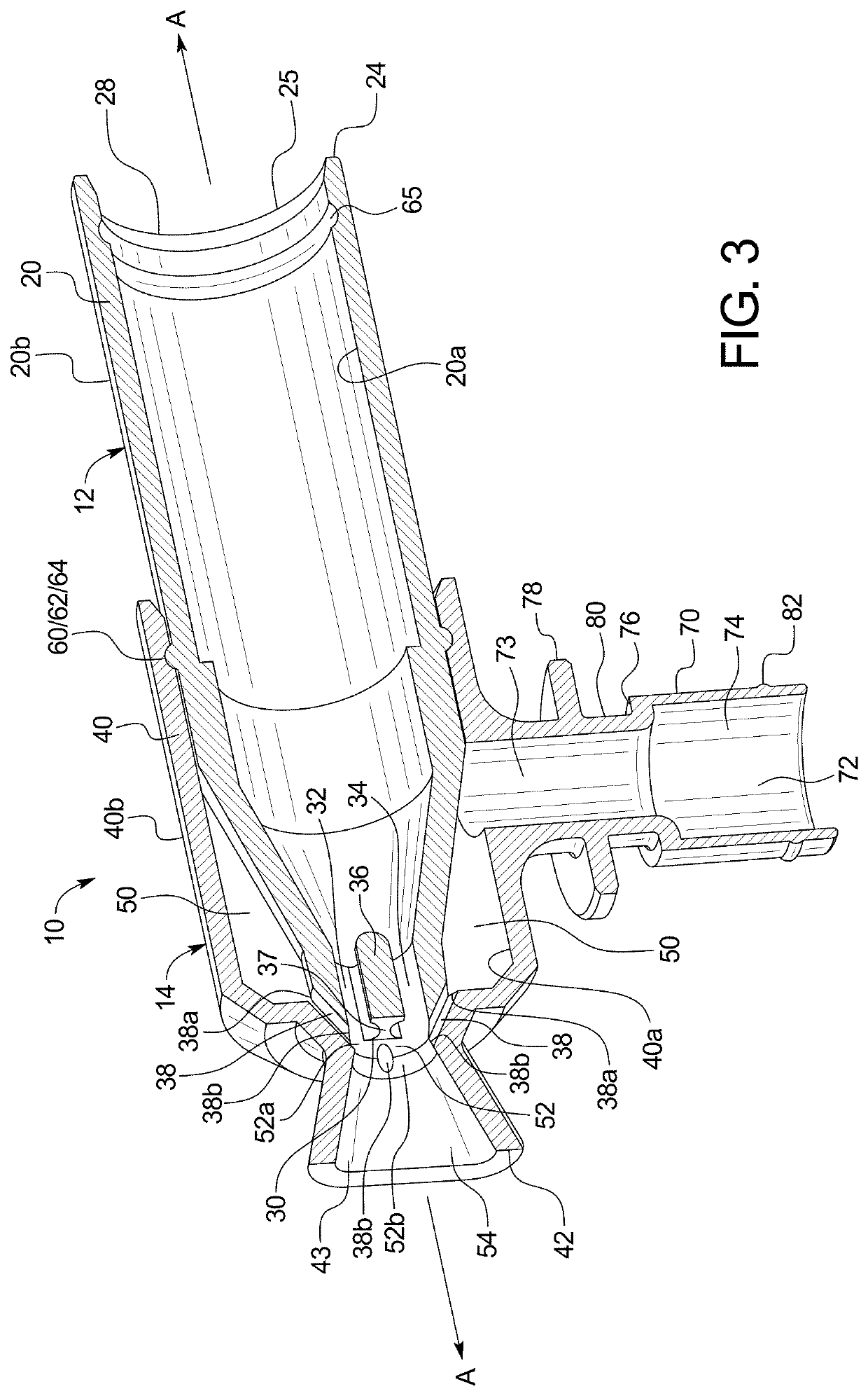
[0037]Referring initially to FIG. 1, an example embodiment of a spray nozzle 10 is shown connected to a dispensing device or dispenser D. The spray nozzle 10 is configured to couple to an end of a mixer or mixing device 114 and a connecting device 112 with a pressurized gas hose 116. Thus, as can be understood, the spray nozzle 10 is disposed between the mixer or mixing device 114 and the connecting device 112 of the dispenser D.

[0038]The dispenser D can be a spray mixer for the mixing and dispensing of at least two components. That is, the dispenser D can be for a multi-component industrial coating packaging system for use in simultaneously dispe...


PUM


Abstract

A spray nozzle for spraying material includes an outlet, a mixing section, an inlet for the material, and a buffer space for pressurized gas. The mixing section is in fluid communication with the outlet. The inlet is in fluid communication with the mixing section. The buffer space is in fluid communication with the mixing section via two or more separate gas supply channels. The inlet comprises a separating wall configured to divide a flow of material to be sprayed into two separate flow passages prior to entry into the mixing section.

Description

BACKGROUNDField of the Invention[0001]The present invention generally relates to a spray nozzle for spraying fluid material. In particular, the present invention relates to a spray nozzle configured to divide a flow of material into two separate flow passages prior to entering a mixing section configured to receive pressurized gas.Background Information[0002]Conventional spray mixers include a mixing device with a spray nozzle attached to an end thereof, a hose for pressurized gas, and an elbow between the hose and the spray nozzle. As a compound exits the mixing device it enters the spray nozzle and combines with the pressurized gas that passes from the hose through the elbow and into the spray nozzle. The spray nozzle, along with the pressurized gas, then sprays the compound on a surface or other structure.SUMMARY[0003]It is an object of the present disclosure to create a spray nozzle capable of spraying at comparatively high flow rates and which the amount of overspray, i.e. the ...

Claims


Application Information

Patent Timeline
IPC IPC(8): B05B7/04
CPCB05B7/0483B05B7/10B05B7/0408B05B7/2472B05B15/63B05B7/0475B05B15/65B05B7/2427B05B7/241
Inventor PELLETIER, RYANTURNER, HAYDENLINDSEY, ROBERT
Owner MEDMIX SWITZERLAND AG
Features
  • R&D
  • Intellectual Property
  • Life Sciences
  • Materials
  • Tech Scout
  • Unparalleled Data Quality
  • Higher Quality Content
  • 60% Fewer Hallucinations
Learn More