Occupant protection device

a technology for occupant protection and occupants, which is applied in pedestrian/occupant safety arrangements, vehicle components, vehicle arrangements, etc., can solve the problems of inability to suppress forward movement of occupants' waists, and inability to accurately restrain occupants, etc., to achieve accurate restraint, suppress collapse and compression, and accurately cover the front of occupants

Active Publication Date: 2021-09-30
TOYODA GOSEI CO LTD
View PDF0 Cites 7 Cited by
  • Summary
  • Abstract
  • Description
  • Claims
  • Application Information

AI Technical Summary

Benefits of technology

[0016]In the occupant protection device with the configuration described above, since the floor airbag device placed in front of the occupant seated on the seat on the floor is configured to be slidable following the slide movement of the seat, at the time of operation, the floor airbag can be inflated with a constant distance from the seat. Therefore, the floor airbag can be inflated so as to accurately cover the front of the occupant from the shin to the knee without being extremely far apart or extremely close to the seat. Furthermore, in the occupant protection device, the seat airbag device is built in a seat portion of the seat and the seat airbag is configured to inflate so as to raise at least the front portion side of the seat portion upward. Therefore, the inflated floor airbag and the seat airbag regulate the forward movement of the buttocks of the occupant and the waist of the occupant can be accurately regulated to move forward. Then, the occupant in which the forward movement of the waist is s

Problems solved by technology

However, in the occupant protection device described in JP-A-2019-34698, since the upper airbag and the lower airbag are arranged on a vehicle body side, for example, when restraining an occupant seated in a seat that is slid significantly backwards with respect to the front windshield and instrument panel, there may be a gap

Method used


Image

  • Occupant protection device
  • Occupant protection device
  • Occupant protection device

Examples


first embodiment

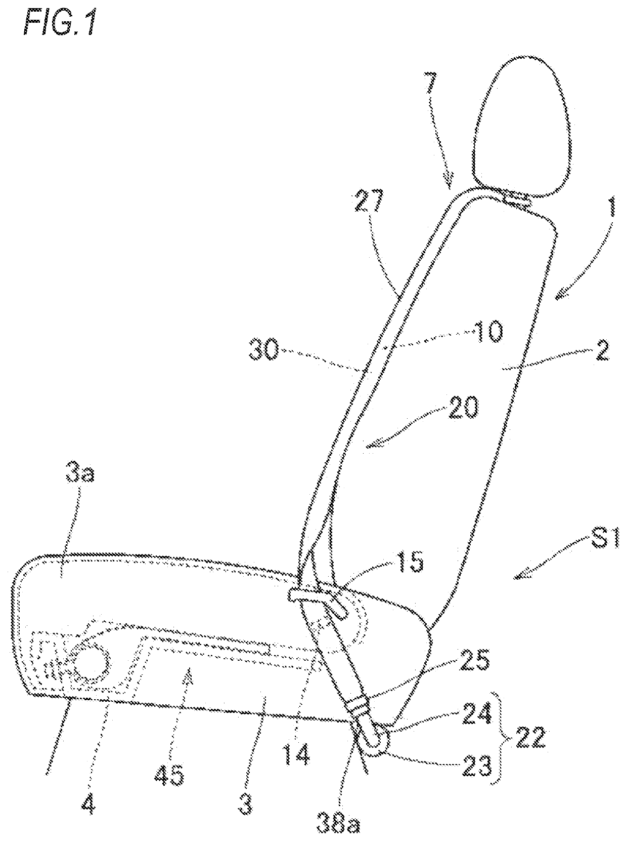
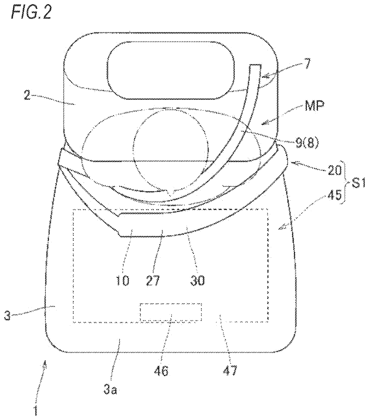
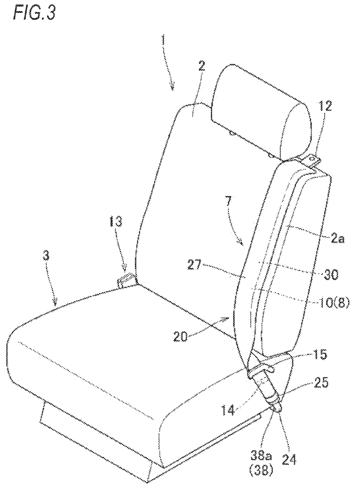
[0045]In the occupant protection device S1 of the first embodiment, when the front collision of the vehicle is detected, the inflator 22 of the front airbag device 20 operates and the inflation gas discharged from the inflator 22 flows into the bag body 31 via the conduit portion 38, Therefore, the bag body 31 ruptures the cover 27 and projects forward and upward from the lap belt 19 to complete the inflation as illustrated by the alternate long and short dash line in FIG. 4. Further, the inflator 46 of the seat airbag device 45 also operates and the inflation gas discharged from the inflator 46 flows into the seat airbag 47, and thus the seat airbag 47 completes the inflation, as illustrated in FIG. 8.

[0046]The occupant protection device S1 of the first embodiment has a configuration including the front airbag device 20 arranged in the area of the lap belt 10 and the seat airbag device 45 built in the seat portion 3 of the seat 1. As illustrated in FIG. 8, the occupant protection d...

second embodiment

[0053]Then, in the occupant protection device S2 of the second embodiment, since the seat 1A is fixed so as to be restricted from moving back and forth with respect to the floor F, the floor airbag device 55 arranged in front of the occupant MP seated on the seat 1A can inflate the floor airbag 60 in a state where the distance to the seat 1A is constant at the time of operation. Therefore, the floor airbag 60 can be inflated so as to accurately cover the front of the occupant MP from the shin ML to the knee MK without being extremely far apart or extremely close to the seat 1A. Therefore, by covering the area from the shin ML to the knee MK with the inflated floor airbag 60, the forward movement of the buttocks of the occupant MP can be restricted and the waist MW of the occupant MP can be restricted from moving forward. Then, as illustrated in FIG. 12, the occupant MP in which the forward movement of the waist MW is suppressed is received by the front airbag 30 which inflates so as...

third embodiment

[0057]Therefore, even in the occupant protection device S3 of the third embodiment, the forward movement of the waist MW can be accurately regulated, and thus the occupant MP can be stably protected.

[0058]In the occupant protection devices S1, S2, and S3 of the embodiments, the inflation completed shape of the front airbag 30 (bag body 31) has a substantially triangular prism shape in which the axial direction is substantially along the left-right direction. Also, when the occupant MP moves the upper body MU closer to the lower body MD by a large extent when the inflation of the front airbag 30 is completed, the bag body 31 is suppressed from being compressed and collapsing so as to bring the upper body restraining surface 35 closer to the thigh abutment surface 34. As a result, the upper body MU of the occupant MP can be accurately restrained by the bag body 31 (front airbag 30). Further, the inflation completed shape of the front airbag is not limited to those of the embodiments a...


PUM


Abstract

An occupant protection device, which protects an occupant seated in a seat, includes: a seat belt; a front airbag device provided with a front airbag which is placed in an area of a lap belt and inflates to cover a front of the occupant when operated; and a seat airbag device provided with a seat airbag which is arranged inside a seat portion in the seat and inflates so as to raise at least a front portion side of the seat portion upward. The front airbag causes inflation gas to flow into the inside and inflates so as to protrude forward and upward when operated and a thigh abutment surface abutting on a thigh of the occupant and an upper body restraining surface restraining an upper body of the occupant are arranged on an outer peripheral surface of the front airbag when the inflation is completed.

Description

CROSS-REFERENCE TO RELATED APPLICATION(S)[0001]This application is based upon and claims the benefit of priority from prior Japanese patent application No. 2020-061819 filed on Mar. 31, 2020, the entire contents of which are incorporated herein by reference.BACKGROUND1. Field of the Invention[0002]The present invention relates to an occupant protection device for protecting an occupant seated in a seat.2. Description of the Related Art[0003]In a recent year, as an occupant protection device, there is provided a device with a configuration including a front airbag which is placed in an area of a lap belt in a seat belt and inflates to cover a front of an occupant and an upper airbag and a lower airbag which respectively inflate in front of the front airbag so that front surface sides are supported by a front windshield and an instrument panel (see JP-A-2019-34698, for example). In this occupant protection device, the front airbag is configured to inflate so as to protrude from the la...

Claims


Application Information

Patent Timeline
IPC IPC(8): B60R21/2338B60R21/207B60R21/206
CPCB60R21/2338B60R2021/23107B60R21/206B60R21/207B60R21/18B60N2/42718B60N2/688
Inventor YAMADA, SHINJIFUKAURA, KAZUMIHAYASHI, TAKEKIICHIMURA, TAKASHIMASUDA, YASUSHISATO, YUJI
Owner TOYODA GOSEI CO LTD
Why Eureka
Try Eureka