

Heat and material exchanger
a technology of heat and material exchangers, applied in indirect heat exchangers, spray nozzles, lighting and heating apparatus, etc., can solve the problems of high manufacturing cost, ineffectiveness, and risk of drop entrainment, and achieve the effect of reducing manufacturing cost and reducing production cos
Pending Publication Date: 2021-09-30
ASSOC POUR LA RECH & LE DEV DES METHODES & PROCESSUS IND (ARMINES)
View PDF0 Cites 0 Cited by
- Summary
- Abstract
- Description
- Claims
- Application Information
AI Technical Summary
Benefits of technology
The invention is a type of exchanger that uses a fan to improve the circulation of gas. The exchanger has two types of zones, and a second collector is used to collect a cooled and concentrated liquid. This second collector is separated from the first collector to prevent mixing of the collected liquids. The technical effects of this invention include improved gas circulation, reduced pressure drop, and efficient heat transfer.
Problems solved by technology
This type of exchanger allows effective exchange of heat and of material but has a major disadvantage linked to the entrainment of liquid drops in the gas flow.
This entrainment of drops constitutes a risk when the liquid is toxic or corrosive.
The implementation of such exchangers is delicate, due to the static pressure of the liquid flowing in the pipe formed by the membranes.
This pressure can cause sealing problems and requires membranes having particular mechanical properties contradictory with permeability to the vapor which make them ineffective and costly to manufacture.
Method used
View moreImage
Smart ImageViewing Examples

Examples
Embodiment Construction
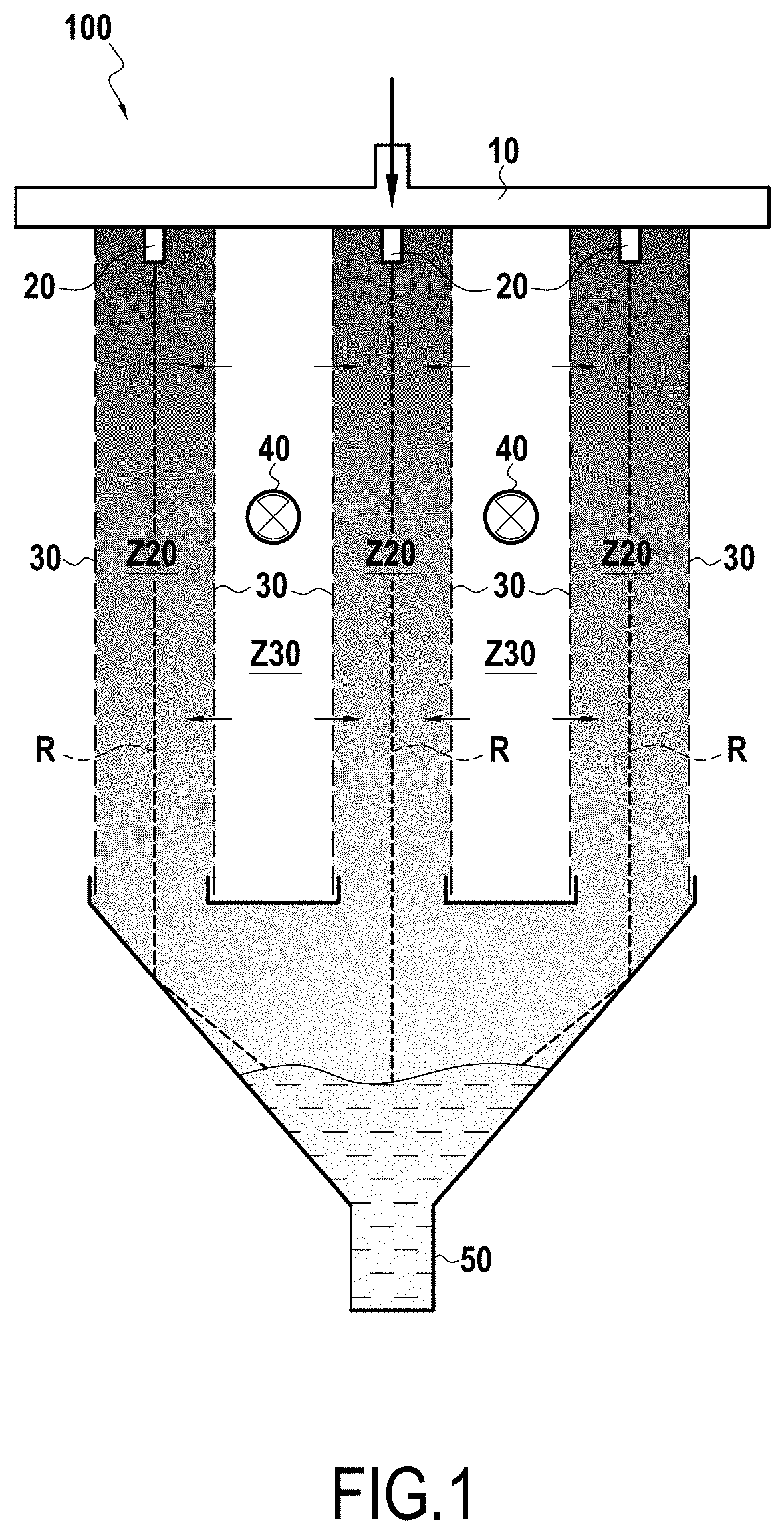
[0069]As previously mentioned, in the embodiment of FIG. 1, the solution recovered in the collector 50 is diluted by the water vapor which has migrated from the zones Z30 through the membrane 30. It is necessary, to be able to re-use it at the input to the pipe 10, to remove the water added to it.
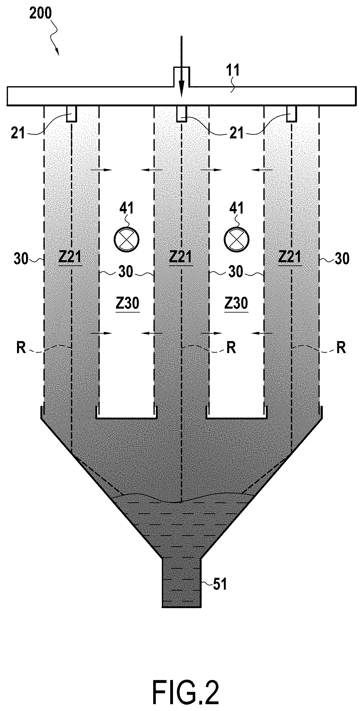
[0070]To carry out this operation, it is possible to head the diluted solution recovered in the collector 50 and to inject it into the pipe 11 of the exchanger of FIG. 2 in order to reduced its temperature and to concentrate it.
Login to View More PUM
 Abstract
This exchanger (100) includes:substantially parallel and vertical membranes (30), permeable to vapor and impermeable to a liquid, these membranes delimiting zones, each of said zones belonging alternately to a first type of zone and to a second type of zone;the zones of said first type including in the upper portion a spray nozzle (20) configured to vaporize a liquid along a plane (R) substantially parallel to the membranes, and in the lower portion a first collector (50), independent and separated from the zones of the second type,a first pipe (10) supplying the spray nozzles (20) of the zones (Z20) of said first type with a liquid.
Description
BACKGROUND[0001]The invention relates to a heat and material exchanger.[0002]Known in the prior art of heat and material exchangers in particular are exchangers using direct contact between a sprayed liquid and a gas. This type of exchanger allows effective exchange of heat and of material but has a major disadvantage linked to the entrainment of liquid drops in the gas flow. This entrainment of drops constitutes a risk when the liquid is toxic or corrosive.[0003]Also known are exchangers allowing an indirect exchange in which the flow is separated by membranes permeable to the vapor and impermeable to the liquid. The implementation of such exchangers is delicate, due to the static pressure of the liquid flowing in the pipe formed by the membranes. This pressure can cause sealing problems and requires membranes having particular mechanical properties contradictory with permeability to the vapor which make them ineffective and costly to manufacture.[0004]The invention proposes a heat...
Claims
Login to View More Application Information
Patent Timeline
 IPC IPC(8): F28D21/00B05B1/24
CPCF28D21/0015B05B1/24
InventorZOUGHAIB, ASSAAD
OwnerASSOC POUR LA RECH & LE DEV DES METHODES & PROCESSUS IND (ARMINES)