Earmuffs having hot packs therein

a technology of earmuffs and hot packs, which is applied in the field of earmuffs, can solve the problems of inconvenience, shortened use period, and increased use time, and achieve the effect of improving the protection effect of the ear region and preventing the risk of losing the hot pack during us

Active Publication Date: 2021-10-28
KIM YEONGMI
View PDF0 Cites 0 Cited by
  • Summary
  • Abstract
  • Description
  • Claims
  • Application Information

AI Technical Summary

Benefits of technology

[0008]The earmuffs according to the present invention allow for the heat generation hot packs to be inserted and used in the ear covers, thereby providing the effect of improving the effect of protecting ear r

Problems solved by technology

However, the conventional earmuffs have a limitation to a warm-keeping function because they form covers configured to simply block the wind.
However, when a heat generation function is provided using a rechargeable battery or battery,

Method used


Image

  • Earmuffs having hot packs therein
  • Earmuffs having hot packs therein
  • Earmuffs having hot packs therein

Examples


first embodiment

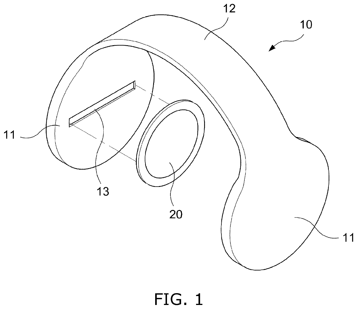
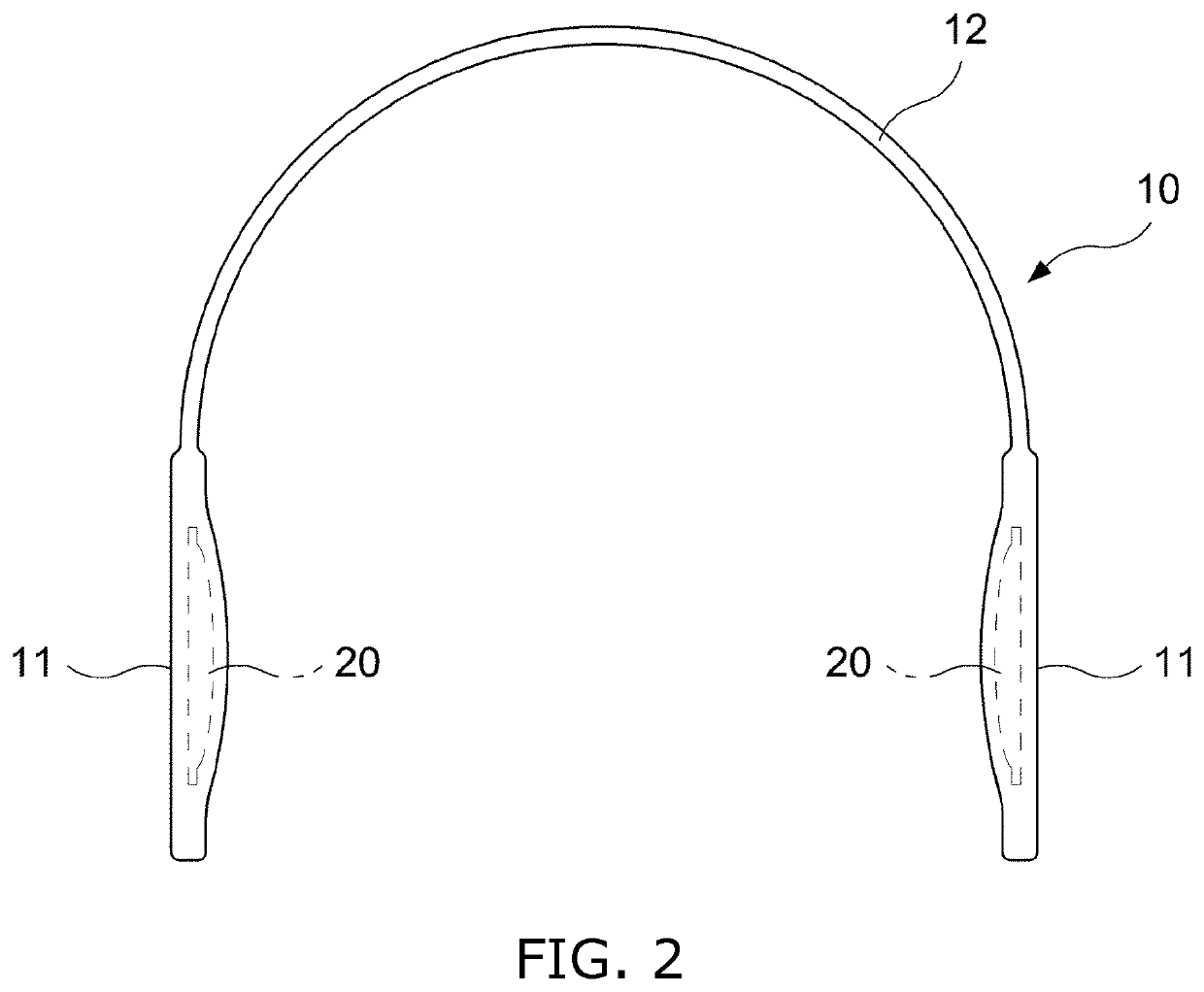
[0020]First, the structure of earmuffs according to the present invention will be described with reference to FIGS. 1 to 5 below.

[0021]The earmuffs 10 according to the present embodiment include a pair of ear covers 11 and a band 12 configured to connect the ear covers 11 to each other.

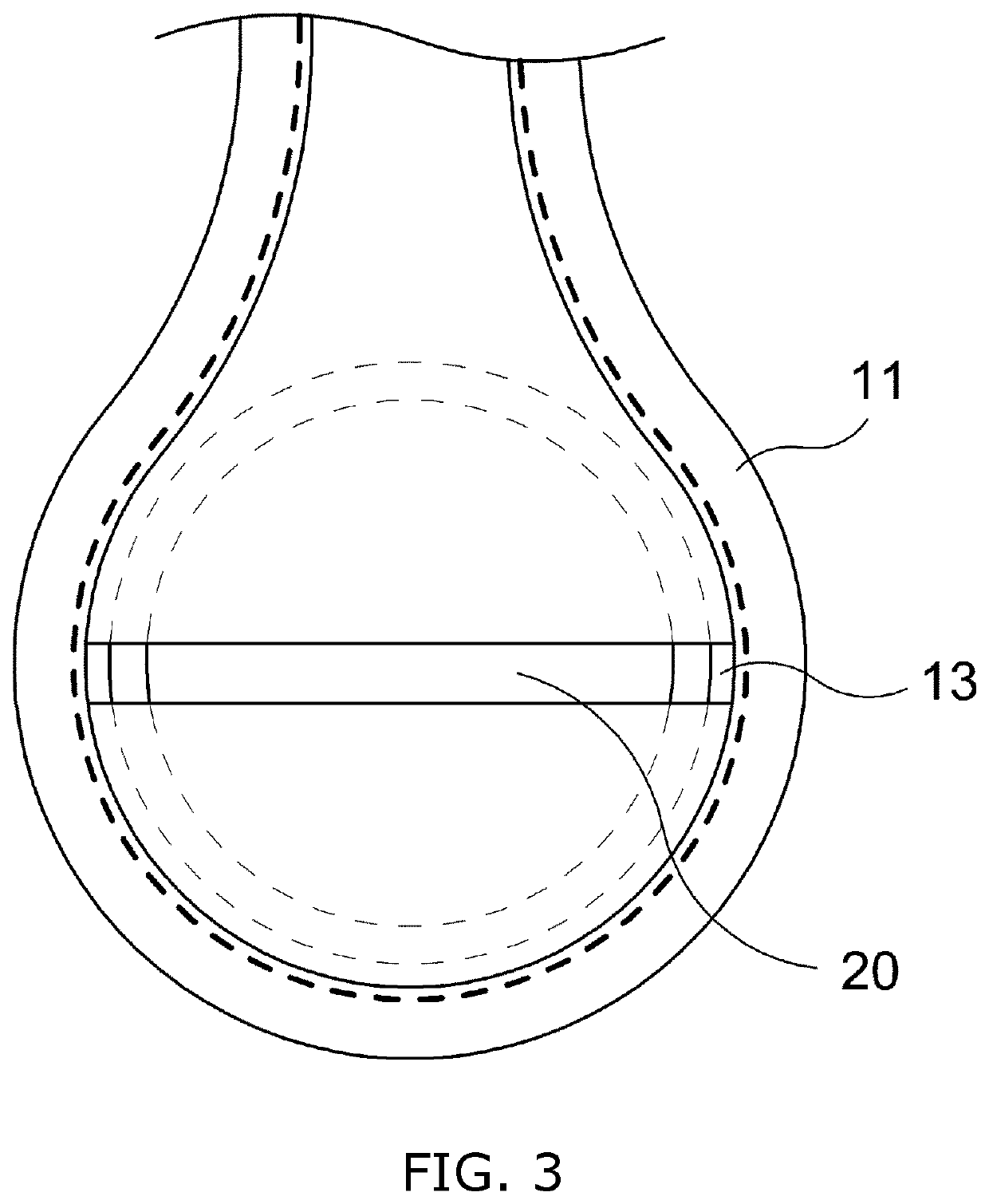
[0022]In this case, it can be seen that the hot packs 20 configured to generate heat are inserted and provided in the ear covers 11.

[0023]For this purpose, reception slots 13 through which the hot packs 20 configured to generate heat may be inserted are formed in the ear covers 11 in lateral directions.

[0024]Operations and effects attributable to the use of the earmuffs according to the present invention, which are configured as described above, will be described below.

[0025]The earmuffs 10 according to the present invention are worn and used on the head part of a human, as shown in FIG. 6. In this case, the hot packs 20 are inserted into both the side ear covers 11 through the reception slots 13, and...

second embodiment

[0030]Meanwhile, FIG. 7 is a view showing a configuration according to the present invention, from which it can be seen that a heat reflection layer 14 configured to minimize thermal loss by reflecting the heat, generated in a corresponding one of the inserted hot packs 20, to the ear regions of a wearer is formed in the inner space of each of the reception slots 13.

[0031]In this case, the heat reflection layer 14 has a mixed composition of 20 to 40% by weight of Teflon, 20 to 40% by weight of aluminum, 10 to 30% by weight of glass fiber, 10 to 30% by weight of nano-silver, 1 to 10% by weight of ceramic resin, and 1 to 10% by weight of sodium hypochlorite.

[0032]When the earmuffs are configured as described above, the heat generated in the hot packs 20 is reflected inward without leaking to the outside, thereby preventing thermal loss and thus improving a warm-keeping effect.

[0033]In particular, Teflon mixed in the heat reflection layer 14 increases the density of the reflection laye...

third embodiment

[0035]Furthermore, FIG. 8 is a view showing a configuration according to the present invention, from which it can be seen that reception slots 13 are formed in lateral directions and an auxiliary slot 13a extends from the center of each of the reception slots 13 in a vertically upward direction.

[0036]When earmuffs are configured as described above, a “T”-shaped cutout structure is formed by the reception slot 13 and the auxiliary slot 13a, and thus the hot packs 20 may be easily inserted and replaced.


PUM


Abstract

The present invention is directed to earmuffs, and is intended to allow for hot packs to be used, thereby improving the effect of protecting ear regions from cold and a cold wave in the winter season. In order to achieve this, the present invention provides earmuffs (10) including a pair of ear covers (11) and a band (12) configured to connect the ear covers (11), wherein reception slots (13) through which hot packs (20) configured to generate heat are inserted and stored are formed in the ear covers (11), respectively.

Description

TECHNICAL FIELD[0001]The present invention relates to earmuffs, and more specifically to earmuffs having hot packs therein, which allow for hot packs to be inserted and used in earmuffs that are intended to protect ear regions from cold in the winter season.BACKGROUND ART[0002]In general, many users use earmuffs for outdoor activities in the winter season. Such earmuffs are provided with a pair of cover members (ear covers) that are formed to allow ear regions to be comfortably positioned therein while entirely surrounding the ear regions.[0003]Furthermore, the cover members are generally used in such a form that they are generally made of a material such as fur or wool to thus improve a warm-keeping property and they can be worn on the head by connecting both the cover members by a band-type elastic member.[0004]However, the conventional earmuffs have a limitation to a warm-keeping function because they form covers configured to simply block the wind. Accordingly, heat generation-t...

Claims


Application Information

Patent Timeline
IPC IPC(8): A42B1/0188A42B1/008
CPCA42B1/0188A42B1/008A61F7/03A61F11/06A61F2007/0277A61F2007/0005A61F2007/0225
Inventor KIM, YEONGMI
Owner KIM YEONGMI
Why Eureka
Try Eureka