Frame structure of loom

a frame structure and loom technology, applied in the field of loom frame structure, can solve the problems of deterioration in the quality of woven fabric to be woven due to vibration of the side frame, the frame structure is slightly vulnerable to horizontal vibration in terms of vibration resistance, and the vibration resistance of the beam can be improved. , the effect of improving the vibration resistan

Active Publication Date: 2021-10-28
TSUDAKOMA KOGYO KK
View PDF0 Cites 6 Cited by
  • Summary
  • Abstract
  • Description
  • Claims
  • Application Information

AI Technical Summary

Benefits of technology

[0022]In contrast, when the frame structure is configured such that the support structure according to the disclosure as described above is the height position setting member on the let-off side, in this frame structure, the side frame is received by the height position setting member on the side surface of the portion on the let-off side, which is the portion where the side frame receives the vibratory force due to the beam vibration. As a result, according to this configuration, the frame structure has improved vibration resistance against the beam vibration.
[0023]Further, in the frame structure configured such that the support structure is the height position setting member disposed on the let-off side of the side frame as described above, the frame structure has further improved vibration resistance against the beam vibration described above when the beam support that supports the warp beam is integrally formed in the support structure. Specifically, in the frame structure configured such that the support structure is the height position setting member disposed on the let-off side of the side frame as described above, the beam support is supported by the support structure when the beam support is configured to be integrally formed in the support structure. In this way, the frame structure has a configuration in which vibratory force due to the beam vibration does not act directly on the side frame. Therefore, according to this configuration, the frame structure has further improved vibration resistance against the beam vibration described above.
[0024]Further, in the frame structure of the loom of the disclosure, it is possible to more effectively improve the vibration resistance against the beating vibration when the frame structure is configured such that the fixed position of the support structure with respect to the side frame is the position of the inner surface of the side frame. Specifically, in a typical loom, the support position of the rocking shaft of the beating device that generates beating vibration as described above in the side frame is the inner surface side of the side frame. Therefore, when the frame structure is configured such that the fixed position of the support structure according to the disclosure with respect to the side frame is the inner surface of the side frame, the support position by the support structure is on the side that receives vibratory force due to the beating vibration, and thus, it is possible to more effectively improve the vibration resistance against the beating vibration.

Problems solved by technology

In such a loom, it is known that violent vibration (so-called beating vibration) is generated in each side frame supporting the rocking shaft due to beating operation by the beating device during weaving.
However, in the frame structure of the loom disclosed in PTL 2, problems such as deterioration in the quality of a woven fabric to be woven due to vibration of the side frame may occur.
Therefore, such a frame structure is slightly vulnerable to horizontal vibration in terms of vibration resistance.
In particular, in recent years, the operation of the loom has tended to be increased in speed, and the vibration of the side frame becomes more violent with the increase in the speed of the loom.
When the side frame vibrates violently like that, each device supported by the side frame including the beating device vibrates, which may adversely affect the weaving and deteriorate the quality of the woven fabric to be woven.
However, in that case, it becomes necessary to manufacture a plurality of types of side frames having different configurations so as to correspond to a plurality of types of warp beams having different diameters, which leads to an increase in the manufacturing cost of the loom.

Method used


Image

  • Frame structure of loom
  • Frame structure of loom
  • Frame structure of loom

Examples


Embodiment Construction

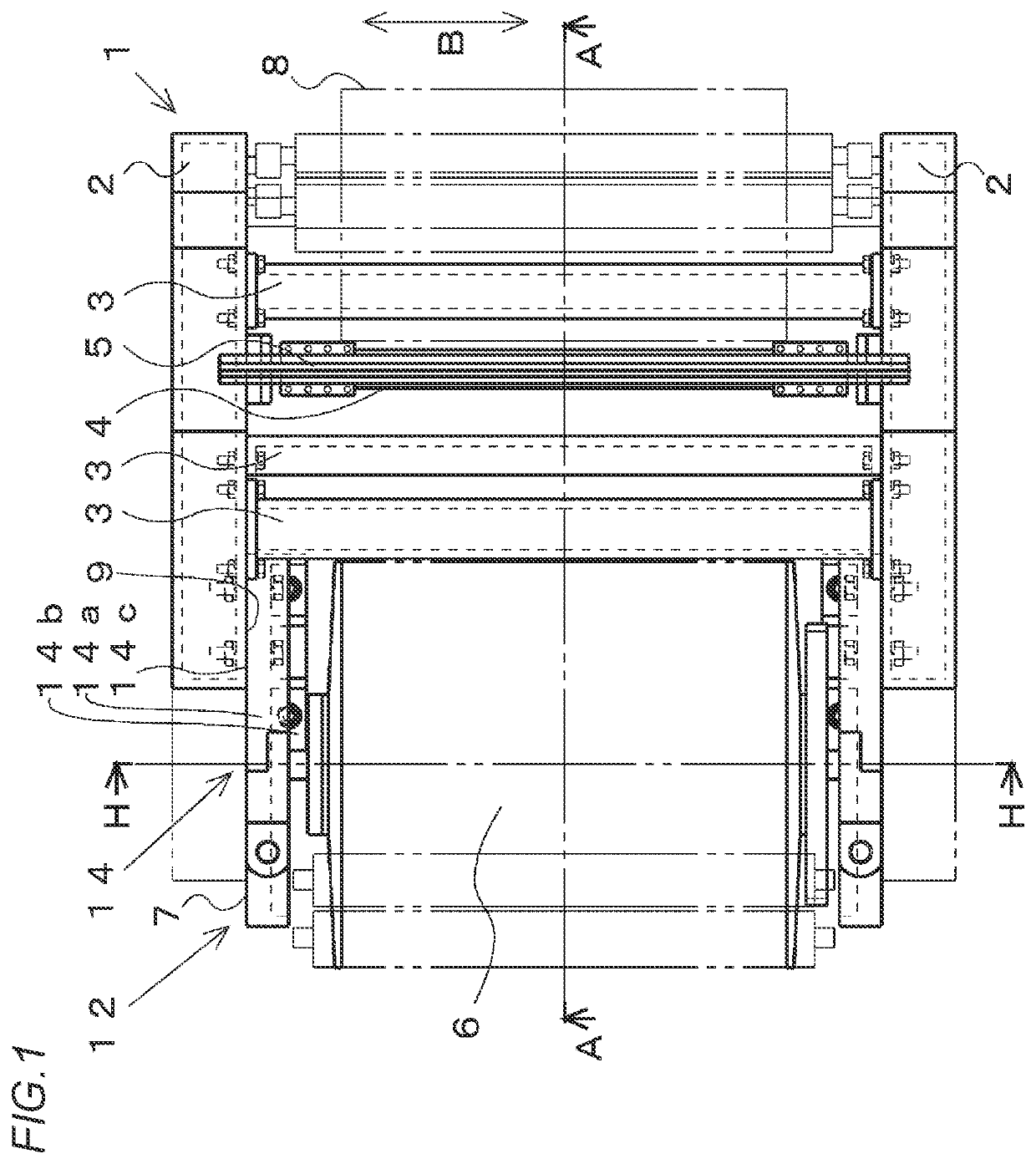
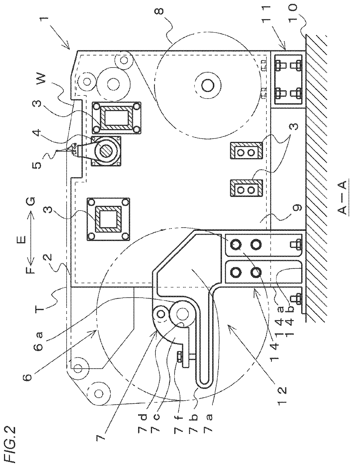
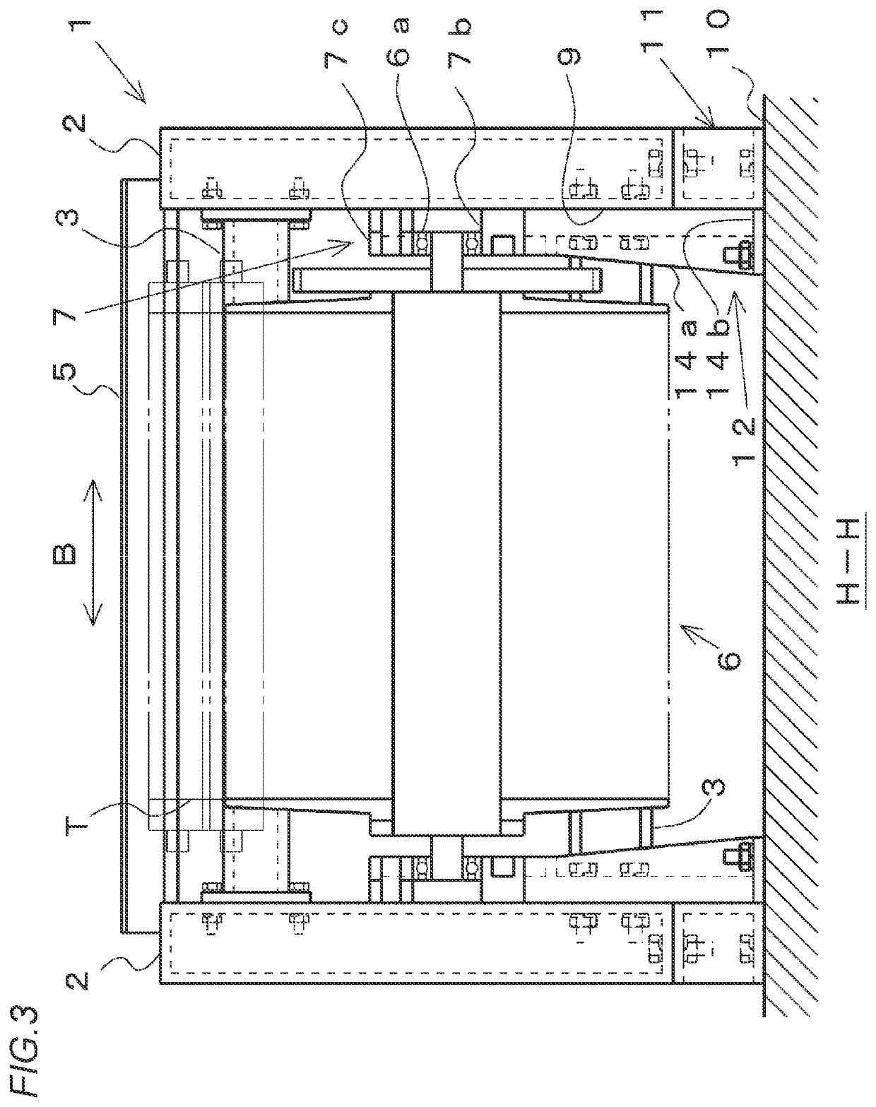
[0028]Hereinafter, an embodiment (the present embodiment) of a frame structure of a loom to which the disclosure is applied will be described with reference to FIGS. 1 to 3.

[0029]In a loom, a frame 1 includes a pair of side frames 2, 2 as a main configuration, and both side frames 2, 2 are connected by a plurality of beam materials 3. Each side frame 2 is formed in a housing shape having a space therein. Both side frames 2, 2 are connected by the beam materials 3 in a state of facing each other in a width direction (thickness direction) thereof.

[0030]Further, the loom is provided with a warp beam 6 for feeding a warp T so as to be supported by both side frames 2, 2 on one side in a front and rear direction (direction orthogonal to a longitudinal direction of the beam materials 3 in a plan view) thereof. Further, the loom is provided with a take-up beam 8 for winding a woven fabric so as to be supported by both side frames 2 on the other side in the front and rear direction thereof.

[...


PUM


Abstract

A frame structure of a loom includes a frame formed by connecting a pair of side frames, to each of which a beam support for supporting a warp beam is fixed, by a plurality of beam materials, and one or more pair of height position setting members arranged between a loom installation surface and each of the side frames. Each of the height position setting members is fixed to the installation surface and the corresponding side frame. The pair of height position setting member are provided as a support structure configured such that a fixed position with respect to the corresponding side frame on at least one of a let-off side and a take-up side is an inner surface or an outer surface of the side frame.

Description

CROSS-REFERENCE TO RELATED APPLICATION[0001]The present application claims priority from Japanese Patent Application No. 2020-075779, filed on Apr. 22, 2020, the entire subject matter of which is incorporated herein by reference.BACKGROUND OF THE INVENTIONField of the Invention[0002]The disclosure relates to a frame structure of a loom that includes a frame formed by connecting a pair of side frames, to each of which a beam support for supporting a warp beam is fixed, by a plurality of beam materials, and one or more pair of height position setting members arranged between a loom installation surface and each of the side frames. Each of the height position setting members is fixed to the installation surface and the corresponding side frame.Background Art[0003]A typical loom includes, as a main configuration, a frame formed by connecting a pair of side frames having a housing shape by a plurality of beam materials. Further, a beam support for supporting a warp beam is attached to ea...

Claims


Application Information

Patent Timeline
Patent Type & Authority Applications(United States)
IPC IPC(8): D03D49/02
CPCD03D49/02D03D49/025D03D49/027D03D49/06D03D49/20
Inventor MYOGI, KEIICHIYAMAGISHI, DAIGOTAMURA, KOICHIYAMA, KAZUYA
Owner TSUDAKOMA KOGYO KK
Why Eureka
Try Eureka