Electric motor and rotor end ring

a technology of electric motor and rotor end, which is applied in the direction of dynamo-electric machines, magnetic circuit rotating parts, magnetic circuit shape/form/construction, etc., can solve the problems of electric motor spin loss, damage or failure of electric motor,

Active Publication Date: 2021-10-28
GM GLOBAL TECH OPERATIONS LLC
View PDF0 Cites 0 Cited by
  • Summary
  • Abstract
  • Description
  • Claims
  • Application Information

AI Technical Summary

Benefits of technology

[0005]According to several aspects of the present disclosure, a rotor end ring for an electric motor includes an annular disk shaped body, a plurality of outlets adapted to allow coolant to flow from a back side of the body to a face of the body, and a recess formed within the face of the body, wherein coolant flowing through the outlets flows across the recess toward an outer circumference of the body, wherein the outer circumference of the body is configured to prevent coolant from flowing across the outer circumference from the face of the body toward the back side of the body.

Problems solved by technology

Electrical currents flowing within an electric motor create heat, and if some of that heat is not removed, damage or failure of the electric motor can occur.
Further, there is a possibility that some of the coolant flowing radially outward will leak back into the air gap between the stator and the rotor, causing spin losses in the electric motor.

Method used


Image

  • Electric motor and rotor end ring
  • Electric motor and rotor end ring
  • Electric motor and rotor end ring

Examples


Embodiment Construction

[0032]The following description is merely exemplary in nature and is not intended to limit the present disclosure, application, or uses.

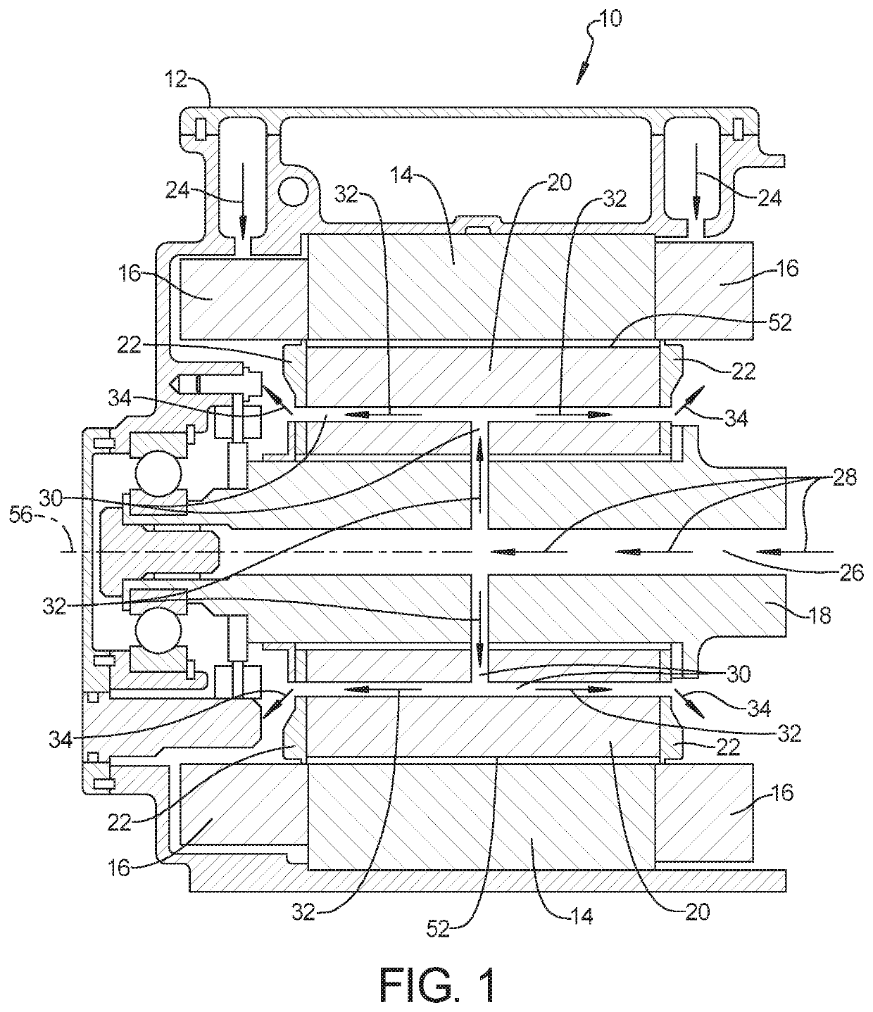
[0033]Referring to FIG. 1, an electric motor 10 according to an exemplary embodiment of the present invention includes a housing 12. A stator 14 is mounted stationary within the housing 12. The stator 14 is generally cylindrical in shape and includes end turn windings 16 on either axial end thereof. A rotatable central shaft 18 is supported by and extends longitudinally within the housing 12. A rotor 20 is mounted onto the central shaft 18 for rotation within the stator 14. The stator 14, central shaft 18 and rotor 20 are all positioned co-axially within the housing 12. A rotor end ring 22 is mounted onto the central shaft 18 adjacent each axial end of the rotor 20. The central shaft 18, the rotor 20 and the rotor end ring 22 rotate unitarily within the housing 12.

[0034]Heat is generated by electric current running through the electric motor 10. Coo...


PUM


Abstract

An electric motor comprises a housing, a stator mounted stationary within the housing and having end turn windings, a rotatable central shaft, a rotor mounted onto the central shaft for rotation within the stator, the stator, central shaft and rotor all positioned co-axially within the housing, a rotor end ring mounted onto the central shaft adjacent an axial end of the rotor, the rotor end ring including a body, a plurality of outlets adapted to allow coolant to flow from a back side to a face of the body, and a recess formed within the face of the body, wherein coolant flowing through the outlets flows across the recess toward an outer circumference of the body, and the outer circumference of the body is configured to prevent coolant from flowing into a circumferential air gap between the stator and the rotor.

Description

INTRODUCTION[0001]The present disclosure relates to an electric motor having a rotor end ring. Specifically, a rotor end ring of the present disclosure provides improved spray of coolant onto the stator end turn windings and reduces the likelihood that coolant will filter back past an outer circumference of the rotor end ring and into the air gap between the stator and the rotor.[0002]Coolant is routed through the rotor to provide cooling of the rotor during operation. Electrical currents flowing within an electric motor create heat, and if some of that heat is not removed, damage or failure of the electric motor can occur. Coolant that flows through the rotor passes out from the rotor at either axial end. As the rotor is spinning, circumferential forces cause the coolant to flow radially outward past the rotor and ultimately onto the end turn windings of the stator.[0003]In current electric motors, the coolant flows radially outward and contacts the end turn windings of the stator ...

Claims


Application Information

Patent Timeline
Patent Type & Authority Applications(United States)
IPC IPC(8): H02K1/32
CPCH02K1/32H02K9/19H02K2213/03H02K5/203H02K5/15
Inventor YANG, XIAOFENGPARRISH, SCOTT E.
Owner GM GLOBAL TECH OPERATIONS LLC
Why Eureka
Try Eureka