Ventilation control unit and ventilation control system

Pending Publication Date: 2021-11-04
DRAGERWERK AG
View PDF0 Cites 0 Cited by
  • Summary
  • Abstract
  • Description
  • Claims
  • Application Information

AI Technical Summary

Benefits of technology

The present invention aims to improve the regulation of gas flow in a ventilation system. It specifically aims to enhance the monitoring of gas flows.

Problems solved by technology

This is especially advantageous for such external gas flow sources, which are not controlled quantitatively via the ventilation system, so that their external gas flow may not be readily known to the ventilation system.
For example, the quality may be compromised by a change in at least one ventilation setting, e.g., the end-expiratory ventilation pressure (PEEP), the ventilation mode, the tidal volume and / or a predefined time characteristic of the ventilation.

Method used


Image

  • Ventilation control unit and ventilation control system
  • Ventilation control unit and ventilation control system
  • Ventilation control unit and ventilation control system

Examples


Embodiment Construction

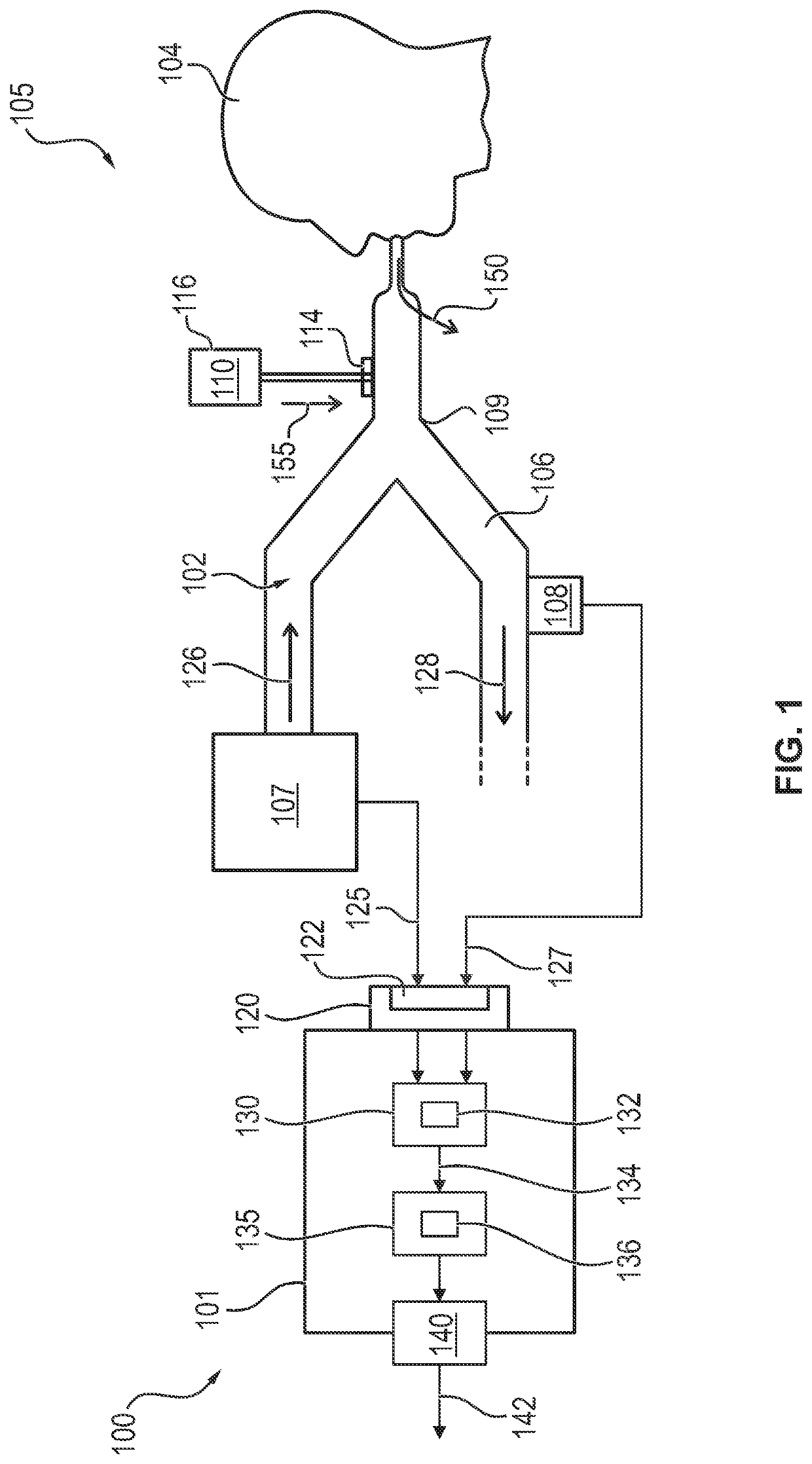
[0062]Referring to the drawings, FIG. 1 shows a schematic view of a first exemplary embodiment of a ventilation control unit 100 according to a first aspect of the present invention within a ventilation system 105 according to a second aspect of the present invention.

[0063]The ventilation control unit 100 is configured to regulate a gas flow 102 within the ventilation system 105 with a ventilation circuit 106 and with an external gas flow source 110 connected to the ventilation circuit 106. The ventilation system 105 has here, furthermore, a ventilator 107 providing an inspiratory gas flow 126. Finally, the ventilation system 105 also has an expiratory gas flow sensor 108, which measures the expiratory gas flow 128. The ventilation circuit 106 passes over a Y-piece 109 to a patient 104 to be supplied with the ventilation system 105. The further course of the gas flow 102 on the exhalation side of the ventilation circuit 106 is not shown in detail and is not relevant for accomplishin...


PUM


Abstract

A ventilation control unit (100), regulating a gas flow (102) within a ventilation system (105), includes a reception module (120), first and second calculation modules (130, 135) and an output module (140). The reception module has a signal interface (122) receiving inspiratory and expiratory flow signals (125, 127) at regular time intervals. The first calculation module calculates a leak flow (132) based on a difference between the current inspiratory gas flow and the current expiratory gas flow, with an external gas flow source (110) separated from a ventilation circuit of the ventilation system. The second calculation module calculates an external gas flow (136) after connecting the external gas flow source to the ventilation circuit based on the leak flow and the difference between the current inspiratory gas flow and the current expiratory gas flow. The output module outputs an output signal (142), based on the external gas flow.

Description

CROSS REFERENCE TO RELATED APPLICATIONS[0001]This application claims the benefit of priority under 35 U.S.C. § 119 of German Application 10 2020 002 656.7, filed May 4, 2020, the entire contents of which are incorporated herein by reference.TECHNICAL FIELD[0002]The present invention pertains to a ventilation control unit for regulating a gas flow within a ventilation system with a ventilation circuit and with an external gas flow source connected to the ventilation circuit. The present invention pertains, furthermore, to a ventilation control and to a process for regulating a gas flow within a ventilation system in the presence of an external gas flow source.TECHNICAL BACKGROUND[0003]An inspiratory gas flow, which is at least partially inhaled by a person, is provided for the person in question by a connected ventilation system during the ventilation of the person. The part of the fed gas that is guided into the mouth of the person is also called patient gas flow. The air exhaled by...

Claims


Application Information

Patent Timeline
IPC IPC(8): A61M16/00A61M11/00
CPCA61M16/024A61M11/00A61M2016/0039A61M2205/3331A61M2016/0042A61M16/0003A61M16/022A61M2016/0018A61M2205/15A61M16/147A61M2230/40A61M16/0891A61M2205/3362A61M16/22A61M2205/3334A61M15/0021A61M2205/3375A61M2205/3317A61M2205/3584A61M2205/3592A61M2205/505A61M2230/005A61M16/0057
Inventor GLAW, TOBIASGDANIEC, PRZEMYSLAW
Owner DRAGERWERK AG
Why Eureka
Try Eureka