Drawer assembly for refrigerator

a refrigerator and drawer technology, applied in the field of refrigerator storage devices, can solve the problem that the partition plate cannot be closely attached to the side wall of the drawer, and achieve the effect of improving the storage effect and improving the storage

Inactive Publication Date: 2021-11-04
HAIER SMART HOME CO LTD
View PDF0 Cites 1 Cited by
  • Summary
  • Abstract
  • Description
  • Claims
  • Application Information

AI Technical Summary

Benefits of technology

[0027]In the present invention, the middle part of the top end of each of the first side wall and the second side wall on the left and right sides of the drawer body is provided with a recess. The recess provides a space for the hand of an operator when the sliding partition plate mechanism slides to the first side wall or the second side wall, that is, the recess is configured to accommodate the hand of the operator, and then, the sliding partition plate mechanism is operated to be attached to the first side wall or the second side wall as much as possible to reduce the gap between the side wall and the partition plate, so that the storage space is maximized when the drawer body does not need to be separated so as to improve the user experience.
[0028]Further, since the middle part of the top end of each of the first side wall and the second side wall is provided with the recess, a user can be guided to operate the middle part of the sliding partition plate mechanism. By shifting the middle part of the sliding partition plate mechanism, the force can be more uniform, and the movement can be smoother, and thereby avoiding tilting caused by unsynchronized movement of the front and rear sides of the sliding partition plate mechanism due to the unbalanced force when the sliding partition plate mechanism is shifted from one end, so as to avoid the resulting gap.

Problems solved by technology

However, when the partition plate in the prior art is moved to two sides, the partition plate usually cannot be closely attached to the side wall of the drawer, and there is a larger gap between the partition plate and the side wall of the drawer, so that a certain storage space is occupied.

Method used


Image

  • Drawer assembly for refrigerator
  • Drawer assembly for refrigerator
  • Drawer assembly for refrigerator

Examples


Embodiment Construction

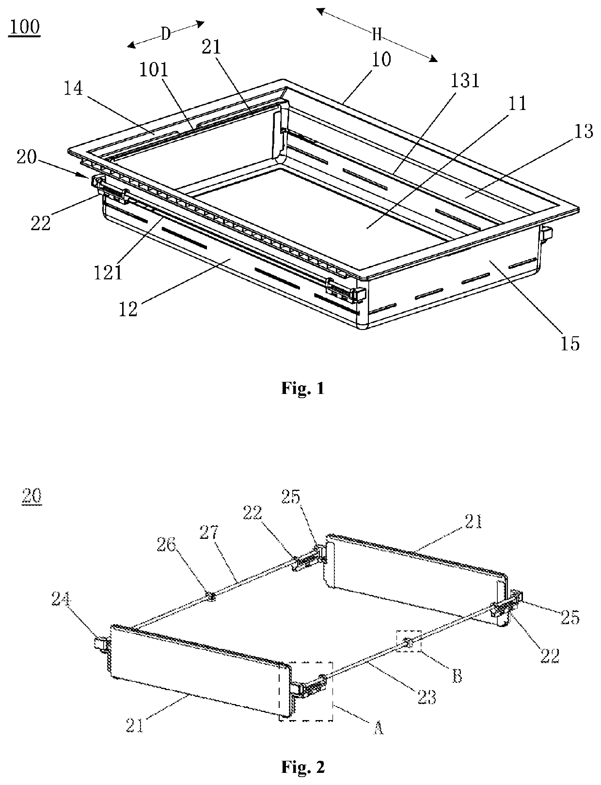
[0039]FIG. 1 is a schematic structural diagram of a drawer assembly according to an embodiment of the present invention. As shown in FIG. 1, the present embodiment provides a drawer assembly 100 for a refrigerator, which includes a drawer body 10 and a sliding partition plate mechanism 20. The drawer body 10 includes a bottom wall 11, a front end wall 12 and a rear end wall 13 which are arranged oppositely along a drawing direction D, and a first side wall 14 and a second side wall 15 which are respectively arranged on two sides of the front end wall 12 and the rear end wall 13, and the bottom wall 11, the front end wall 12, the rear end wall 13, the first side wall 14 and the second side wall 15 jointly define an accommodating cavity for holding objects. The sliding partition plate mechanism 20 is parallel to the first side wall 14 and located in the accommodating cavity, and the sliding partition plate mechanism 20 is configured to be capable of sliding along the left-and-right di...


PUM


Abstract

Provided is a drawer assembly for a refrigerator. The drawer assembly comprises: a drawer body, wherein the drawer body comprises a bottom wall, a front end wall and a rear end wall which are arranged opposite each other in a drawing-in or drawing-out direction, and a first side wall and a second side wall respectively arranged at two sides of the front end wall and the rear end wall, such that an accommodation cavity for placing an article is defined; and a slidable partition plate mechanism configured to slide in the left and the right direction of the drawer body. The middle parts of top ends of the first side wall and the second side wall are respectively provided with a recess for providing clearance when the slidable partition plate mechanism is controlled to slide to the first side wall or to the second side wall, such that the slidable partition plate mechanism is attached to the first side wall or to the second side wall as much as possible. The drawer assembly can provide a storage space in a maximized manner.

Description

FIELD OF THE INVENTION[0001]The present invention relates to the technical field of refrigerator storage devices, and particularly relates to a drawer assembly for a refrigerator.BACKGROUND OF THE INVENTION[0002]Generally, a drawer for storage is disposed inside a refrigerator chamber. In order to improve the utilization efficiency of the drawer, a partition plate is disposed inside the drawer, and the drawer is separated into different spaces by the movement of the partition plate to meet storage requirements.[0003]When an object with larger volume needs to be stored, it is necessary to move the partition plate to the side wall of the drawer so as to maximize the space of the drawer.[0004]However, when the partition plate in the prior art is moved to two sides, the partition plate usually cannot be closely attached to the side wall of the drawer, and there is a larger gap between the partition plate and the side wall of the drawer, so that a certain storage space is occupied.BRIEF ...

Claims


Application Information

Patent Timeline
Patent Type & Authority Applications(United States)
IPC IPC(8): F25D25/02A47B88/477
CPCF25D25/025A47B2210/175A47B2210/0091A47B88/477A47B88/975A47B57/58A47B57/585
Inventor WEI, DONGZHANG, JIANWANG, NINGNIE, JUNWU, GUANGRUI
Owner HAIER SMART HOME CO LTD
Why Eureka
Try Eureka