
Wood chipper knife

a wood chipper and knife technology, applied in the field of wood chipper knives, can solve the problems of increasing the amount of chips which cannot be used for further processing, increasing the amount of small particles, and high cost of arrangements, so as to minimize the tendency of clogging, effectively guide the separation of chips, and minimize the effect of clogging

Pending Publication Date: 2021-11-11
ANDRITZ AB
View PDF3 Cites 0 Cited by
  • Summary
  • Abstract
  • Description
  • Claims
  • Application Information

AI Technical Summary

Benefits of technology

The present invention aims to improve a wood chipper knife to reduce clogging and improve chip quality. The invention includes a pressure release recess with a bottom that is preferably angled between 70-93 degrees, and more preferably at about 89-91 degrees. This angle helps to transfer separated chips smoothly without tumbling and further minimizes clogging risks. Overall, the invention helps to improve the performance of the wood chipper knife.

Problems solved by technology

However, typical for the industry today is that the knives used have the same basic form independent of what wood to chip and process, which can result in an increased amount of chips which cannot be used for further processing due to wrong sizes (too small, i.e. particulate, or oversized).
However, such arrangements are expensive and tend to increase the amount of small particles, which cannot be used for further processing and therefore have to be scrapped.
Although the known wood chipper knife constitutes an improvement over some other previously known wood chipper knives, in practice it shows that chipper knives of this kind can run into trouble when one tries to cut wood that does not release chips easily, that is, when chips tend to adhere to each other and form so-called cards because their wood fibers are not totally separated from each other.
The trouble that arises then is that there is both a tendency toward clogging of the chipping machinery and toward poor quality of the chips produced, which is detrimental both from a production point of view as well as from an environmental point of view.

Method used


Image

  • Wood chipper knife
  • Wood chipper knife

Examples


Embodiment Construction

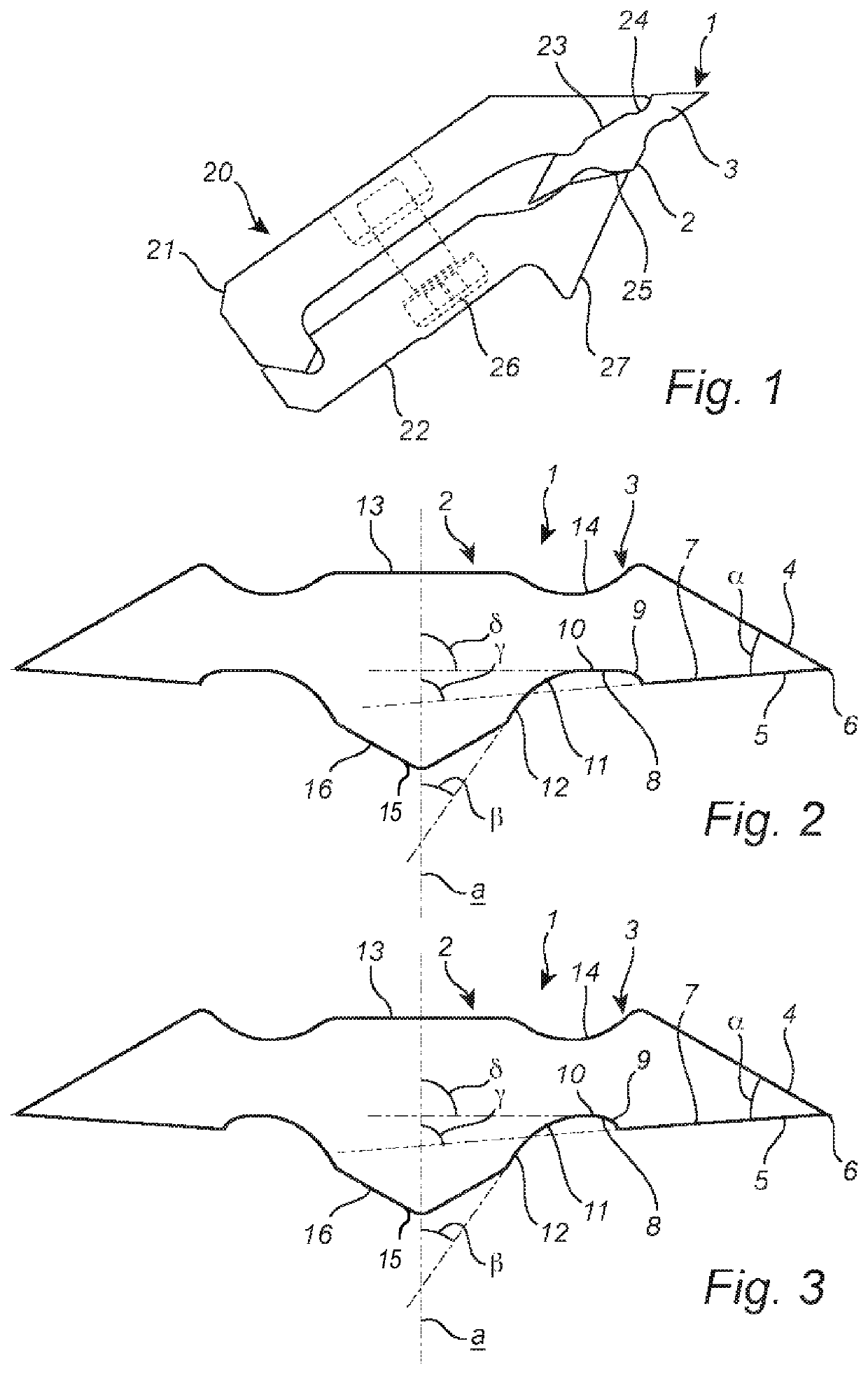
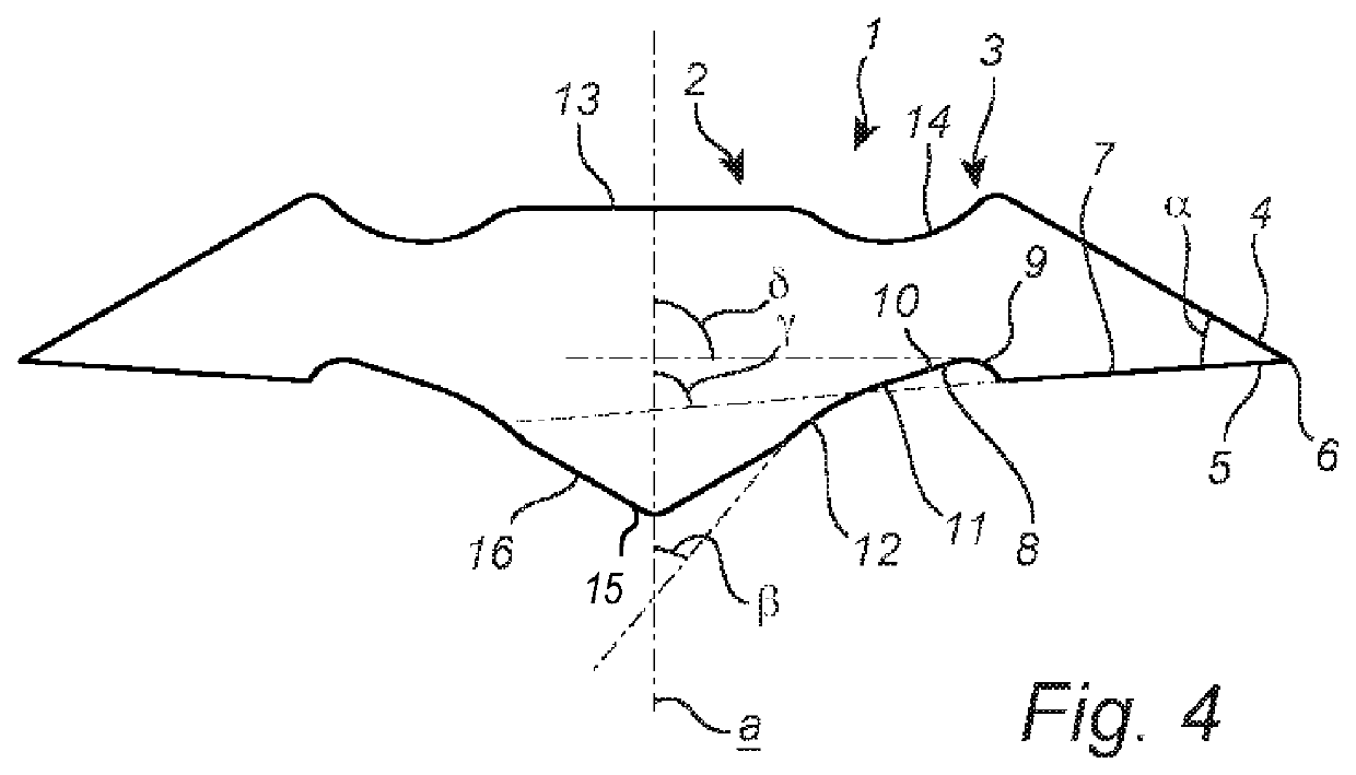
[0027]In the drawings and the description, the same references are used for all three embodiments of the wood chipper knife 1, as the embodiments differ only in certain dimensional aspects. Further, as far as directional indications are used in the description and the claims, such as top and bottom, these refer to the drawings and can therefore differ from reality. Finally, as machinery for wood chipping is well-known, only the wood chipper knife embodiments and a knife holder 20 for these are described and shown.

[0028]A wood chipper knife 1 according to the first embodiment is shown in FIG. 1 mounted in a knife holder 20. The knife holder 20 is, just like the wood chipper knife 1 itself, shown in a cross-sectional view. It extends into the drawing plane along the whole length of the wood chipper knife 1, which in reality means for at least some tenth of a meter.

[0029]The knife holder 20 comprises a base 21 on top and a clamp 22 underneath. Both are held together by means of a bolt ...


PUM


Abstract

A wood chipper knife includes a knife body and, in relation to a vertical axis of the wood chipper knife, at least one cutter side, which comprises a top cutting edge portion and a bottom cutting edge portion that intersect to form a cutting edge. The bottom cutting edge portion includes a planar wood attacking portion, which begins at the cutting edge and towards the knife body is followed by a recess. The recess is a pressure release recess, which, from the wood attacking portion, abruptly falls to a bottom of the pressure release recess, and which stretches from the wood attacking portion to the knife body. The knife body comprises a chip guiding portion, which, from the pressure release recess, rises towards the knife body.

Description

TECHNICAL FIELD[0001]The present invention concerns a wood chipper knife comprising a knife body and, in relation to a vertical axis (or plane of symmetry) of the wood chipper knife, at least one cutter side, which comprises a top cutting edge portion and a bottom cutting edge portion that intersect at an acute angle to form a cutting edge, wherein the bottom cutting edge portion comprises a planar wood attacking portion, which begins at the cutting edge and towards the knife body is followed by a recess.BACKGROUND[0002]Wood chipper knives are used in chippers to process logs into wood chips. The wood chips are produced from many different wood species, which have different density, moisture content, fiber length and other specific characteristics, such as resinous or frozen, and are used for further processing.[0003]In order for wood chipper knives to work properly and to provide well separated wood chips of an even size, which is important for further processing, they have to be s...

Claims


Application Information

Patent Timeline
IPC IPC(8): B27L11/00B02C18/18
CPCB27L11/005B02C18/18B27G13/04
Inventor ENGNELL, MATS
Owner ANDRITZ AB
Features
  • Generate Ideas
  • Intellectual Property
  • Life Sciences
  • Materials
  • Tech Scout
  • Unparalleled Data Quality
  • Higher Quality Content
  • 60% Fewer Hallucinations
Learn More