Element for a floating dock and a floating dock

a technology for floating docks and elements, applied in the direction of prefabricated sub-unit hulls, vessel construction, transportation and packaging, etc., can solve problems such as crush injuries

Pending Publication Date: 2021-11-11
MARINE IP
View PDF0 Cites 1 Cited by
  • Summary
  • Abstract
  • Description
  • Claims
  • Application Information

AI Technical Summary

Benefits of technology

[0026]Preferably, the intermediate portion is connected to the first end portion and the second end portion such that, in use, when a load is placed on the element the connections between the end portions and the intermediate element become more secure. Suc...

Problems solved by technology

This is in contrast to many existing systems, where a watercraft may rock or ot...

Method used


Image

  • Element for a floating dock and a floating dock
  • Element for a floating dock and a floating dock
  • Element for a floating dock and a floating dock

Examples


second embodiment

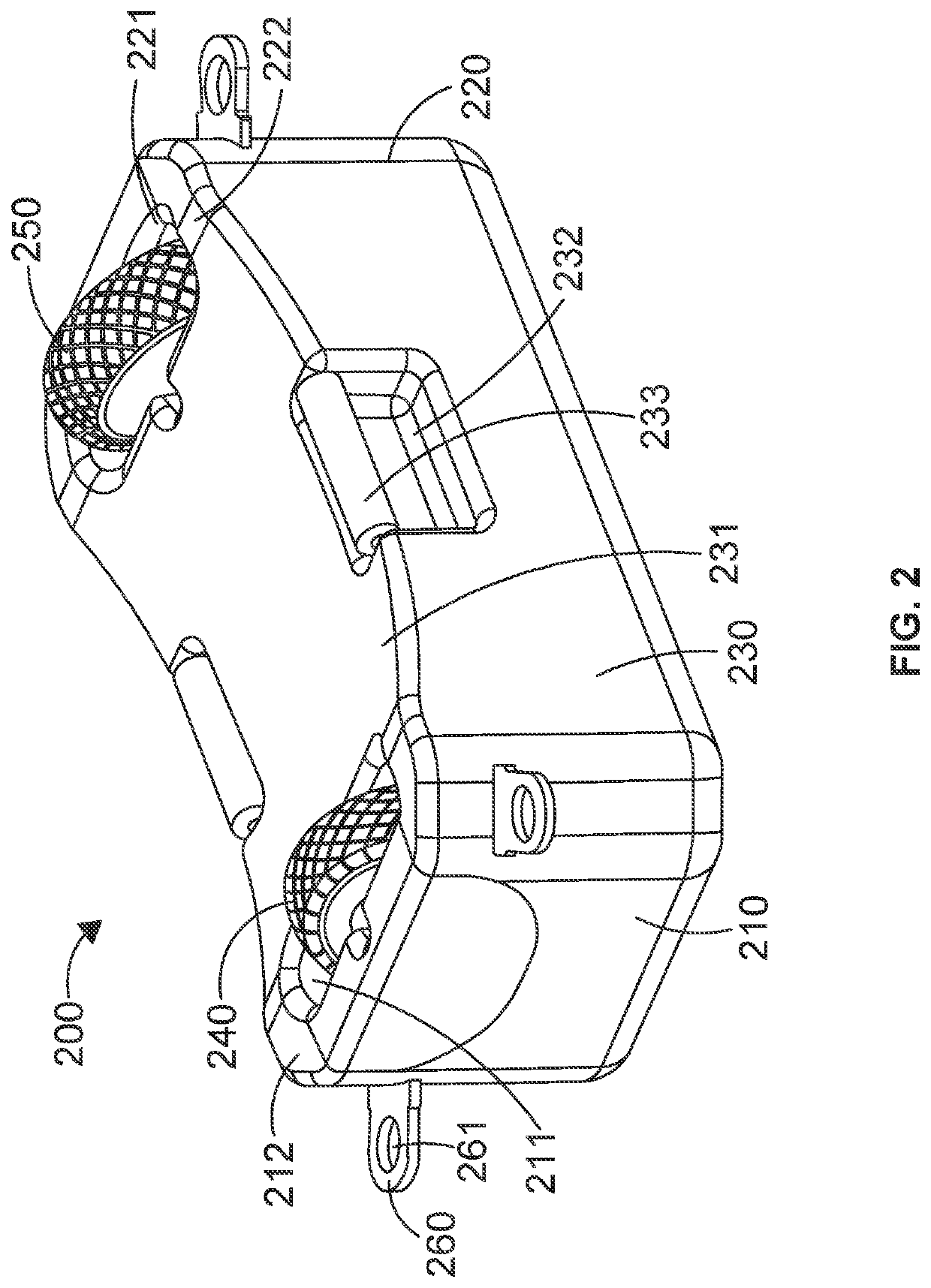
[0063]Referring now to FIG. 2, there is depicted an element 200 according to the present invention.

[0064]Element 200 again comprises a first end portion 210, a second end portion 220 and an intermediate portion 230. As previously described in relation to FIG. 1, the first end portion 210, second end portion 220 and intermediate portion 230 are integrally formed such that the element 200 is a single, continuous structure. Again, the total width of the element 200 depicted in FIG. 2 is around 1 m, although other sizes are envisaged.

[0065]The first end portion 210 comprises a first rotatable support member 240 in the form of a single wheel mounted on an axle (not shown) within the first end portion 210. The single wheel comprises a pneumatic tire with tread. The wheel lies substantially within an indentation 211 located in the first end portion 210, with some of the wheel protruding above a top surface 212 of the first end portion.

[0066]The axle is located within a slot within the inde...
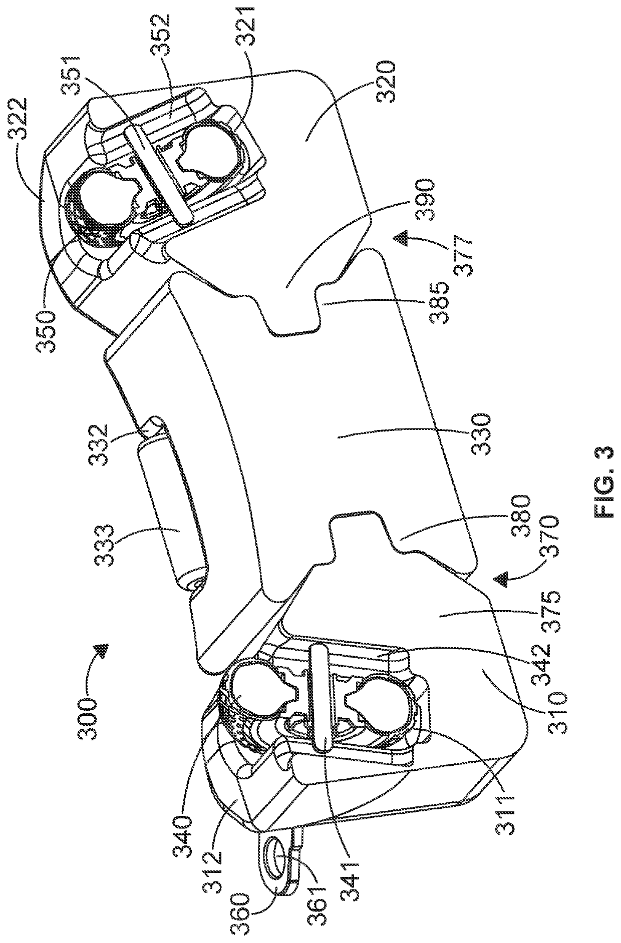
third embodiment

[0073]To form the complete element 300, the first end portion 310 is reversibly connected to the intermediate portion 330, and the second end portion 320 is reversibly connected to the intermediate portion 300. As such, the intermediate portion 330 lies between the first end portion 310 and the second end portion 320. Similarly as described in relation to FIG. 2, this third embodiment of the invention comprises a first rotatable support member 340 in the form of a single wheel mounted on an axle 341 within the first end portion 310. Again, the single wheel comprises a pneumatic tire with tread. The wheel lies substantially within an indentation 311 located in the first end portion 310, with some of the wheel protruding above a top surface 312 of the first end portion.

[0074]The axle 341 is located within a slot 342 within the indentation 311. As can be seen in FIG. 3, the slot 342 extends substantially the entire height of the indentation 311 and is found in two opposing walls of the...


PUM


Abstract

An element for use in a watercraft is provided comprising a first rotatable support member mounted on the element such that the position of the first rotatable support member relative to the element can be varied by a user. A floating dock comprising at least one element is also provided.

Description

CROSS-REFERENCE TO RELATED APPLICATIONS[0001]This application claims priority under the Paris Convention to Great Britain Application Number GB2006446.5, filed on May 1, 2020, the entire content of which is incorporated herein by reference.FIELD OF INVENTION[0002]The present invention relates to an element for a floating dock and a floating dock comprising the element.BACKGROUND[0003]Modular floating docks are well known in the art and are frequently created via the assembly of a number of floating subunits. These subunits or elements include various geometric shapes connected together to provide a floating dock with the shape, size and support capabilities desired. Such modular floating docks are popular, as they provide a convenient way to construct a dock or other floating platform of any shape and size based on a consumer's needs.[0004]It is also known to use such modular systems to construct floating docks that can be driven on to by a watercraft under its own power. Here, the ...

Claims


Application Information

Patent Timeline
IPC IPC(8): B63C1/02
CPCB63C1/02B63C1/04B63B3/02B63B35/34E02B3/064
Inventor DAVISON, CHRISTOPHER
Owner MARINE IP
Why Eureka
Try Eureka