
Washing machine and control method therefor

a technology of washing machine and control method, which is applied in the field of washing machines, can solve problems such as damage to laundry, and achieve the effects of increasing washing power, washing power, and washing machine improvemen

Pending Publication Date: 2021-11-11
LG ELECTRONICS INC
View PDF0 Cites 0 Cited by
  • Summary
  • Abstract
  • Description
  • Claims
  • Application Information

AI Technical Summary

Benefits of technology

This approach allows for improved washing performance with reduced laundry damage by applying stronger washing power in a controlled manner, enabling faster rotational speeds and varied motion patterns that distribute laundry effectively.

Problems solved by technology

Although the recently developed front-loading washing machine is capable of implementing various motions, a motion with enhanced washing power may cause damage to laundry and a motion causing less damage to the laundry provides insufficient washing power.

Method used


Image

  • Washing machine and control method therefor
  • Washing machine and control method therefor
  • Washing machine and control method therefor

Examples


first embodiment

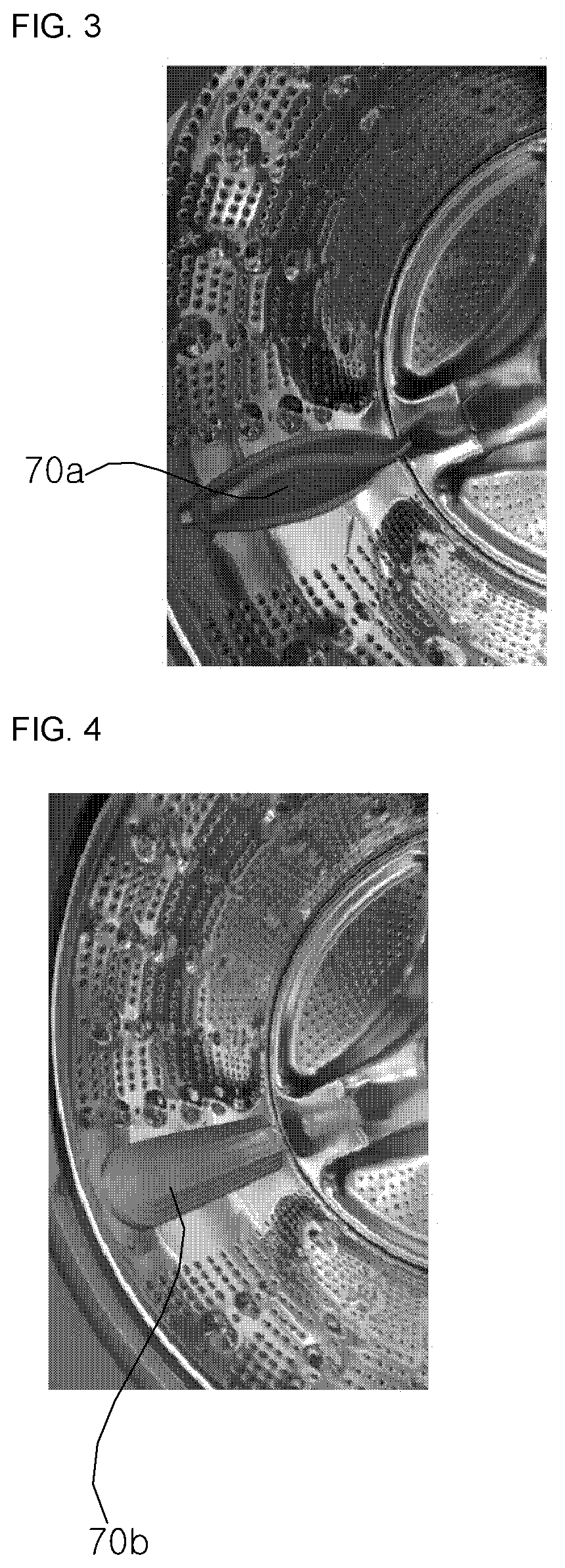
[0095]FIG. 4 is a perspective view showing a part of an inner circumferential surface of a drum of a washing machine according to the present disclosure, the washing machine which has a lifter of a height lower than that of a conventional washing machine. FIG. 5(a) is a plan view of a lifter shown in FIG. 4, and FIG. 5(b) is a cross-sectional view of FIG. 5(a) taken away along line I-I′.

[0096]Referring to FIGS. 4 and 5, a lifter 70b made separately from the drum 60 and disposed on the inner circumferential surface of a drum 60 has a height equal to higher than 10 mm and equal to lower than 20 mm. The washing machine according to the first embodiment of the present disclosure includes the lifter 70b of a height lower than that of the conventional lifter 70a in order to implement various motions. The height of the lifter 70b may be between 10 mm and 20 mm. The term “between” refers to a value within a range equal to or higher than a lower limit value and equal to or lower than an uppe...

second embodiment

[0110]As shown in FIGS. 6 and 7, the washing machine according to the present disclosure may include a lifter 70c integrally formed with the drum 60.

[0111]Referring to FIGS. 6 and 7, the inner circumferential surface of the drum 60 may be divided into a lifter portion 67 and an embossed portion 68. In the inner circumferential surface of the drum 60, two or more lifters 67 spaced apart from each other at a predetermined interval along a circumferential direction of the drum may be formed. That is, in a case where three lifter portions 67 are formed in the inner circumferential surface of the drum 60, the lifter portions 67 may be disposed to form an angle of 120° relative to each other. As shown in FIG. 6, in the lifter portions 67, a lifter 70c having a height lower than that of the conventional lifter 70a may be formed integrally with the drum 60.

[0112]In the washing machine according to the second embodiment, the lifter 70c may be formed in each of a plurality of liter portions 6...


PUM


Abstract

Disclosed is a control method for a washing machine having three or more lifters inside a drum. The control method includes: positioning the lifters on an outer side of a first area including a drum lower portion, and positioning laundry on the first area; performing a first rotation step to rotate the drum in a first direction so that one of the lifters is positioned on the first area and the laundry is positioned on the lifter positioned on the first area; and performing a second rotation step to rotate the drum in a second direction opposite to the first direction, so that the lifters are positioned on the outer side of the first area and the laundry is positioned on the first area, wherein the first rotation step and the second rotation step are performed alternately and repeatedly.

Description

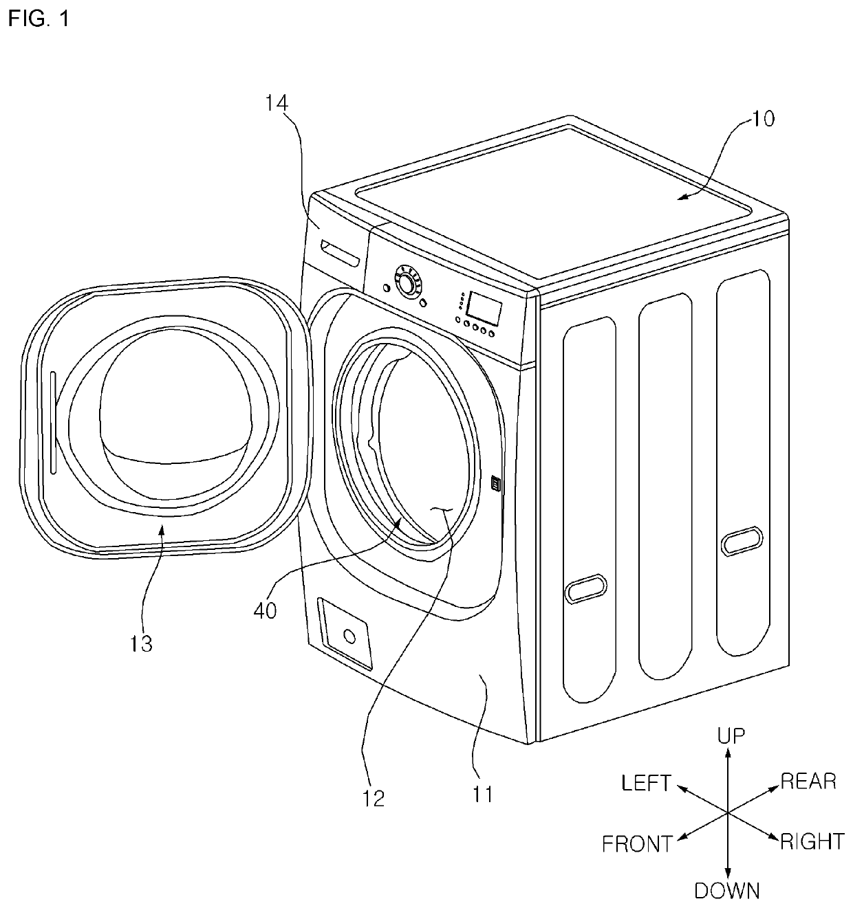
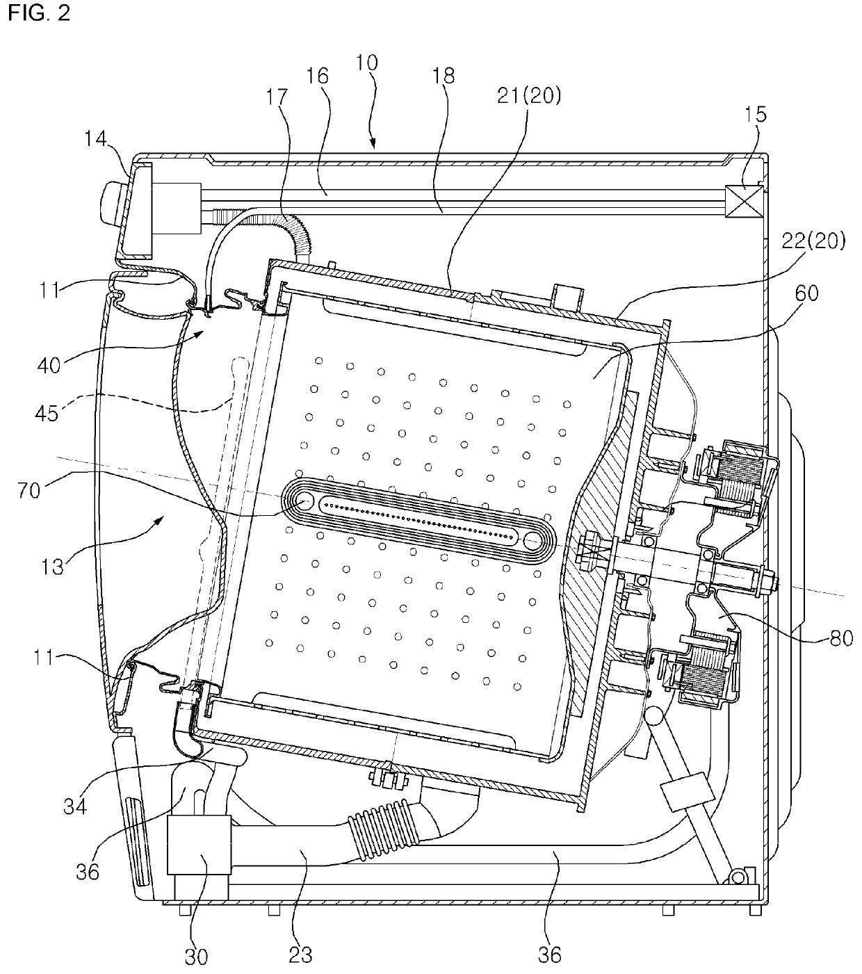
CROSS-REFERENCE TO RELATED APPLICATIONS[0001]This application is a National Stage application under 35 U.S.C. § 371 of International Application No. PCT / KR2019 / 011221, filed on Aug. 30, 2019, which claims the benefit of Korean Patent Application No. 10-2018-0103080, filed on Aug. 30, 2018 and Korean Patent Application No. 10-2019-0101925, filed on Aug. 20, 2019. The disclosures of the prior applications are incorporated by reference in their entirety.BACKGROUND OF THE INVENTIONField of the Invention[0002]The present disclosure relates to a washing machine and a control method therefor, and more particularly to a washing machine capable of implementing a new motion and a control method therefor.Related Art[0003]A washing machine is a general term indicating a device for removing a contaminant stuck to clothes, bedding, etc. (hereinafter, referred to as ‘the laundry’) using a chemical disintegration of water and a detergent and a physical operation such as a friction between water and...

Claims


Application Information

Patent Timeline
Patent Type & Authority Applications(United States)
IPC IPC(8): D06F37/06D06F37/30D06F33/36
CPCD06F37/06D06F2105/48D06F33/36D06F37/304D06F35/006Y02B40/00D06F34/18D06F39/087D06F39/088D06F2103/04D06F2103/18D06F2105/02D06F33/34D06F23/025
Inventor IM, MYUNGHUNJUNG, HWANJINKIM, SUNGGYUNKIM, JAEHYUNWOO, KYUNGCHUL
Owner LG ELECTRONICS INC
Learn More