
Closestool flushing control method

A control method and technology for toilets, which are applied to flushing equipment with water tanks, flushing toilets, water supply devices, etc., can solve the problems of insufficient flushing force, large water consumption, waste, etc., and achieve volume and weight reduction. The effect of reducing water consumption

Inactive Publication Date: 2015-08-19
CHONGQING JIAOTONG UNIVERSITY
View PDF8 Cites 0 Cited by
  • Summary
  • Abstract
  • Description
  • Claims
  • Application Information

AI Technical Summary

Problems solved by technology

[0003] Most of the current toilets are integrated with a water tank. When the toilet is not in use, the water in the water tank becomes idle water. Since the use time of the household toilet is mainly concentrated in the morning and night, during more than ten hours during the day, the water in the water tank is almost completely In an idle state, from the perspective of improving the utilization rate of water resources, the utilization rate of water in the water tank is very low, and the amount of idle water is very considerable, which is undoubtedly a huge waste; in addition, when the toilet flushes the dirt, its The water outlet at the upper brush ring flow channel and the bottom sewage channel exit at the same time, so that the water pressure is separated, and the flushing force is insufficient. ; Although the flushing operation using the toilet water tank can provide a large instantaneous water pressure, the water consumption of one flush is about 5-6 liters, which is large in water consumption and poor in economy

Method used


Image

  • Closestool flushing control method
  • Closestool flushing control method
  • Closestool flushing control method

Examples


Embodiment Construction

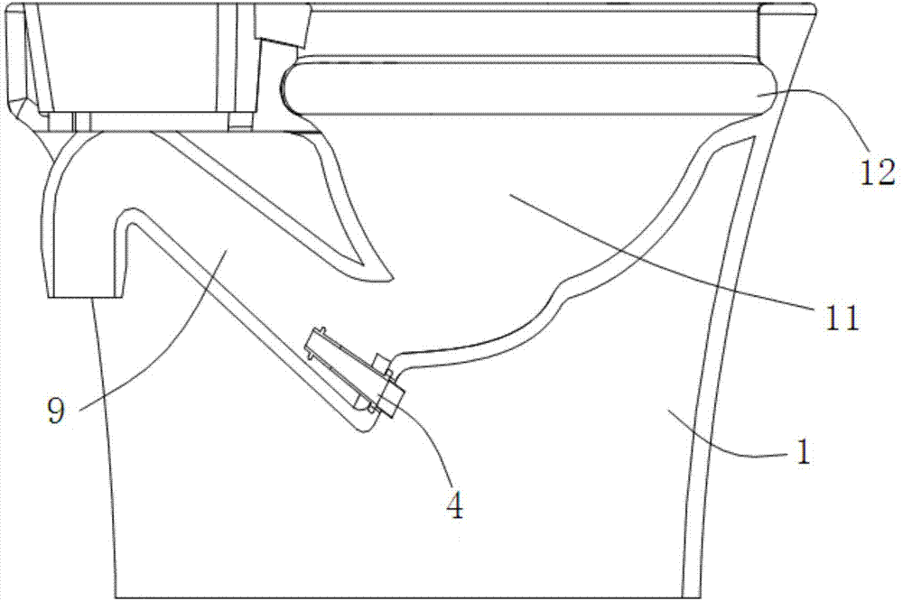
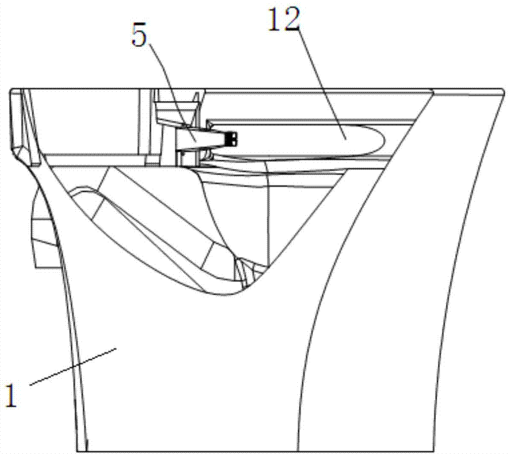
[0027] Such as Figures 1 to 4 Shown: the flushing control method of the toilet of the present embodiment, comprises the following steps:

[0028] P1: trigger the flush switch 22 provided on the toilet 1; the flush switch 22 can be a mechanical button or an automatic sensing part;

[0029] P2: The electric control valve II 24 located in the flushing pipe II is opened, and the electric control valve II 24 is kept in the open state for M seconds and then closed; The water outlet II is connected;

[0030] P3: When the electric control valve II24 is closed, the electric control valve I23 provided in the flushing pipe I is opened, and the electric control valve I23 is kept open for N seconds and then closed; the flushing pipe I is connected to the water supply pipe network and connected with The water outlet I at the sewage channel 9 is connected;

[0031] P4: When the electric control valve I23 is turned off, the electric control valve II24 is opened, and the open state of the ...


PUM


Abstract

The invention discloses a closestool flushing control method. The closestool flushing control method includes the steps that P1, a flushing switch on a closestool is triggered; P2, an electric control valve II arranged in a flushing pipe II is turned on, the electric control valve II is turned off after the turn-on state of the electric control valve II is kept for M seconds, and the flushing pipe II is connected to a water supply pipe network prior to being communicated with a water outlet II in the side wall of a seat flowing passage; P3, an electric control valve I arranged in a flushing pipe I is turned on while the electric control valve II is turned off, and the electric control valve I is turned off after the turn-on state of the electric control valve I is kept for N seconds, and the flushing pipe I is connected to the water supply pipe network prior to being communicated with a water outlet I in a drainage passage; P4, the electric control valve II is turned on while the electric control valve I is turned off, and the electric control valve II is turned off after the turn-on state of the electric control valve II is kept for R seconds. The closestool flushing control method has the advantages that high instantaneous water pressure can be provided, so that high flushing force is achieved, the inner side wall of the closestool can be flushed cleanly and sewage can be drained away; meanwhile, water consumption quantity is decreased effectively, and economy is improved.

Description

technical field [0001] The invention relates to a flushing control method, in particular to a toilet flushing control method. Background technique [0002] With the progress of society, the popularity of toilets in family bathrooms is getting higher and higher, which indicates that people's quality of life is gradually improving, but with the popularization of toilets, new problems also follow. [0003] Most of the current toilets are integrated with a water tank. When the toilet is not in use, the water in the water tank becomes idle water. Since the use time of the household toilet is mainly concentrated in the morning and night, during more than ten hours during the day, the water in the water tank is almost completely In an idle state, from the perspective of improving the utilization rate of water resources, the utilization rate of water in the water tank is very low, and the amount of idle water is very considerable, which is undoubtedly a huge waste; in addition, when...

Claims


Application Information

Patent Timeline
Patent Type & Authority Applications(China)
IPC IPC(8): E03D5/10E03D11/08E03D11/17
CPCE03D5/10E03D11/08E03D11/17
Inventor 李军王艺颖兰兵德陈里里
Owner CHONGQING JIAOTONG UNIVERSITY
Learn More