Floor panel for forming a floor covering

a technology of floor panels and floor coverings, applied in flooring, construction, building construction, etc., can solve the problems of insufficient resistance of couplings to unlocking, high cost of achieving and applying them, etc., and achieve the effect of convenient installation, strong connection, and sufficient strength

Active Publication Date: 2021-11-18
FLOORING IND LTD
View PDF0 Cites 0 Cited by
  • Summary
  • Abstract
  • Description
  • Claims
  • Application Information

AI Technical Summary

Benefits of technology

[0004]The aim of the invention consists in that a floor covering of such floor panels is easy to install, however, that at the same time still sufficient strength is obtained in the floor covering, more particularly sufficiently strong connections can be realized between the floor panels, such in combination with production techniques which keep the production costs of the floor panels limited.
[0037]According to a possible embodiment of the invention, the floor panel shows the characteristic that the aforementioned lower hook-shaped part, at the distal side of its distal end, is free from mechanical vertically active locking parts. More particularly, herein it is recommended that in the coupled condition a space is present behind the distal end of the lower hook-shaped part. Preferably this means that only in the first and the second contact zone vertically active locking parts are present, thus, on only two locations which are situated opposite to each other. The advantage hereof is that tolerance differences, more particularly production tolerances, can be absorbed more smoothly and thus are less critical in the production of the floor panels.
[0038]According to another possible embodiment of the invention, the floor panel shows the characteristic that the aforementioned lower hook-shaped part, at the distal side of its distal end, indeed is provided with one or more mechanical vertically active locking parts, which then cooperate(s) with a locking part, provided for this purpose, of an adjoining floor panel. A disadvantage therein then is that the allowable production tolerances are more critical, however, contrary thereto then there is the advantage that a vertical locking is obtained at three locations, namely in the first contact zone, in the second contact zone and at the distal end of the respective hook-shaped part.
[0087]It is noted that both in the preceding as in the following description, a “floating support point” means that overlapping tolerances are avoided and / or a theoretical space is used in the profile shapes which is very small, preferably is less than 0.2 mm and still better less than 0.1 mm, and preferably a desired value in the order of magnitude of 0.05 mm. The floating support point facilitates joining, however, under load still offers sufficient support without too many height differences.

Problems solved by technology

However, realizing and applying those is costly.
However, it is known that such coupling parts realized in one piece mostly offer a not so strong connection; either, the connection is too taut and the floor panels cannot be interconnected or only interconnected by damaging them, or the coupling does not offer enough resistance against unlocking.

Method used


Image

  • Floor panel for forming a floor covering
  • Floor panel for forming a floor covering
  • Floor panel for forming a floor covering

Examples


Embodiment Construction

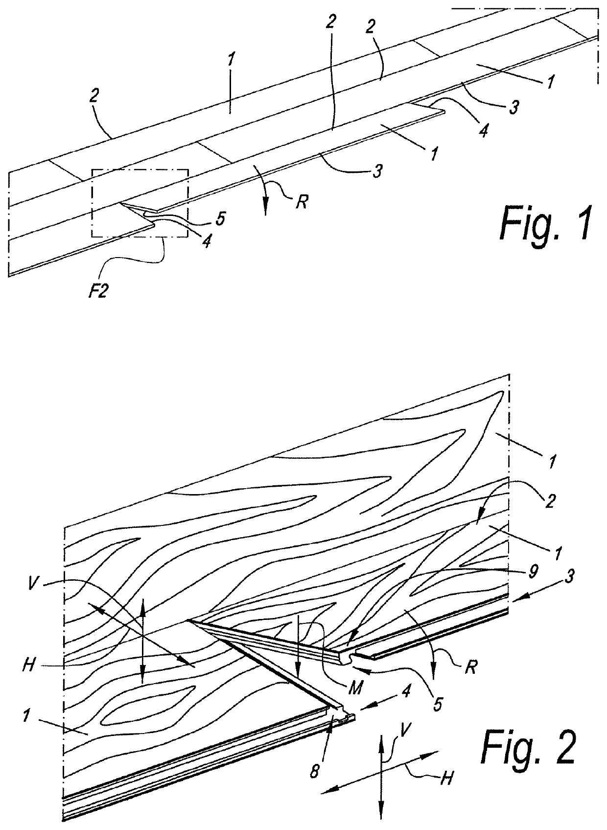
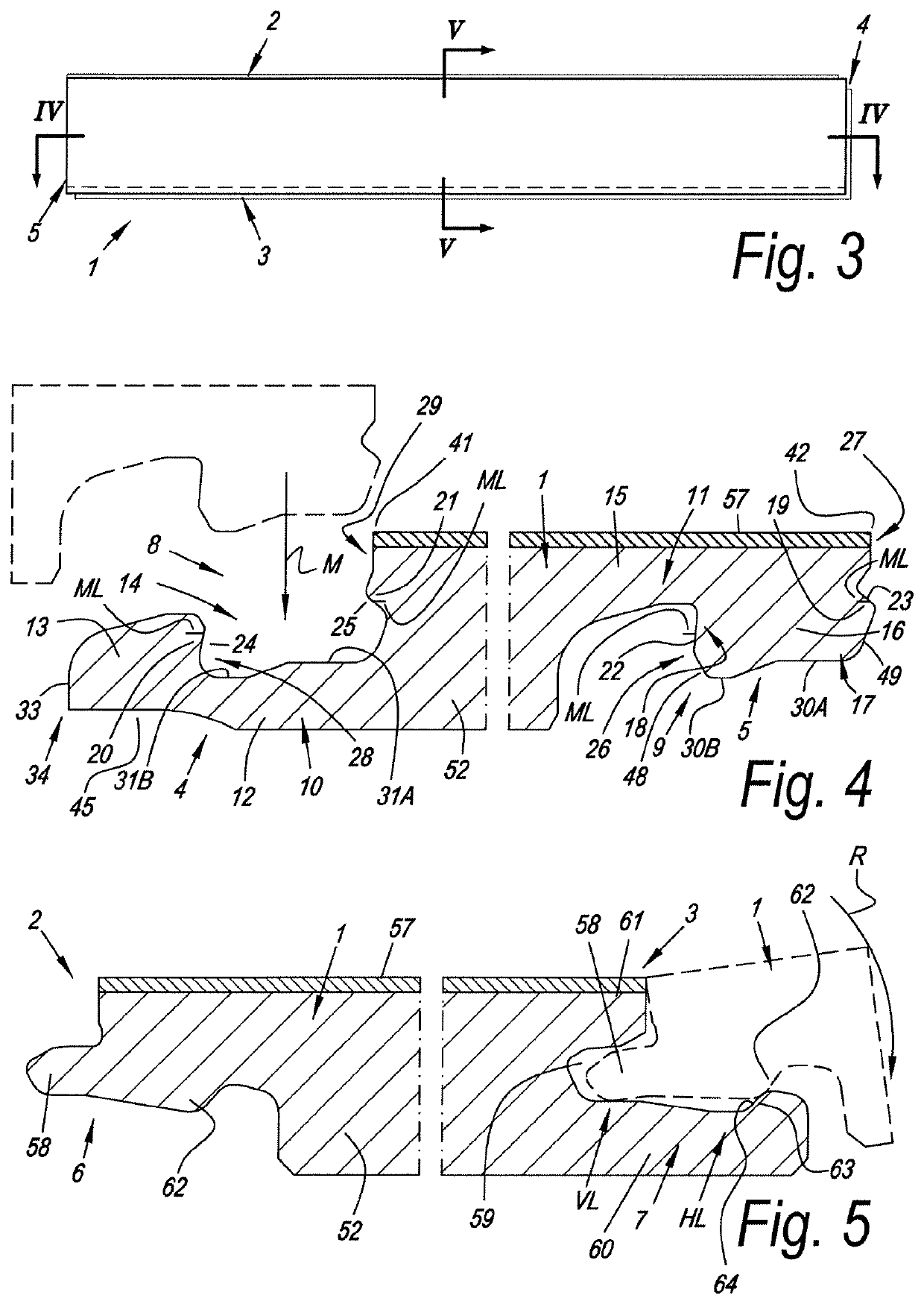
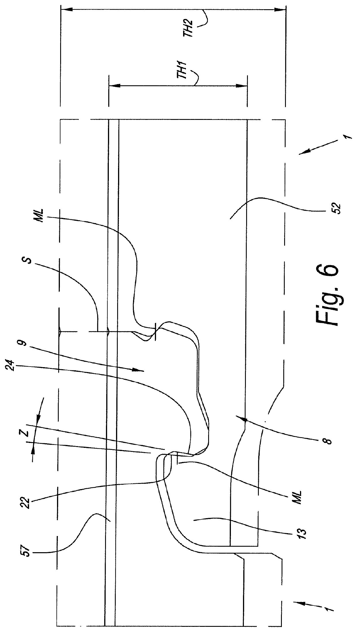
[0098]As represented in FIGS. 1 and 2, the invention relates to floor panels 1 for forming a floor covering, which floor panels 1 comprise a first pair of opposite edges 2-3 and a second pair of opposite edges 4-5.

[0099]The represented floor panels 1 are figured such at their edges that they are mutually coupleable according to the so-called fold-down principle, which is a principle known as such and which consists in that such floor panels 1 can be coupled to each other at the first pair of edges 2-3 by a turning movement R and at the second pair of edges 4-5 can be coupled to each other by a downward movement M, wherein the downward movement M is the result of the turning movement R and thus is effected substantially simultaneously. Herein, the floor panels 1 also are configured such at their edges 2-3 and 4-5 that finally a locking is effected in vertical direction V as well as in horizontal direction H, this latter perpendicular to the respective edges.

[0100]As represented in FI...


PUM


Abstract

A floor panel arranged to be installed according to the fold-down principle, with a first pair and a second pair of edges. The second pair of edges coupling parts are arranged to be coupled to each other by a downward movement with two contact zones at opposite sides of a male part which fits into a female part. The ratio between the horizontal distance between the middle of the first contact zone and the middle of the second contact zone, and the vertical distance between the middle of the first contact zone and the middle of the second contact zone is more than 5, and / or wherein well-defined support points are applied.

Description

[0001]This application is a continuation of U.S. application Ser. No. 16 / 496,230, filed Sep. 20, 2019, which is a 371 Nationalization of PCT / IB2018 / 051898, filed Mar. 21, 2018, which claims the benefit, under 35 U.S.C. 119(e), of U.S. provisional application No. 62 / 474,494, filed on Mar. 21, 2017.BACKGROUND OF THE INVENTIONField of the Invention[0002]This invention relates to a floor panel for forming a floor covering, more particularly for forming a floor covering which can be installed on an underlying surface.[0003]More particularly, the invention relates to floor panels which can be coupled to each other by means of mechanical coupling parts.SUMMARY OF THE DISCLOSURE[0004]The aim of the invention consists in that a floor covering of such floor panels is easy to install, however, that at the same time still sufficient strength is obtained in the floor covering, more particularly sufficiently strong connections can be realized between the floor panels, such in combination with pro...

Claims


Application Information

Patent Timeline
Patent Type & Authority Applications(United States)
IPC IPC(8): E04F15/02
CPCE04F15/02038E04F2201/0153E04F2201/0138E04F15/02E04F15/107
Inventor DE RICK, JAN EDDY
Owner FLOORING IND LTD
Why Eureka
Try Eureka