Lift and tilt device, baler equipped therewith and method of its operation

a technology of tilt device and baler, which is applied in the direction of pressing, loading/unloading, and gathering refuse, etc., can solve the problems of reducing the service life of the baler

Pending Publication Date: 2021-12-02
SCHWELLING HERMANN
View PDF7 Cites 0 Cited by
  • Summary
  • Abstract
  • Description
  • Claims
  • Application Information

AI Technical Summary

Benefits of technology

The invention aims to create a lifting and tilting device and a baler that can effectively empty containers with minimal upward progression. The device is designed to be simple, reliable, and inexpensive to construct, while requiring minimal floor space.

Problems solved by technology

The problem here is that the available headroom above the filling opening is limited, and so during emptying the collector trolley should rise as little as possible from the filling opening.
Furthermore, the problem exists that the floor space required for approaching and inserting the collector trolley into the mounting device of the lift-and-tilt device should be as small as possible next to the actual baler in order to keep the overall floor space required for the operation of the baler to a minimum.
However, such a conveyor belt requires a lot of floor space in addition to the rest of the vertical box baler, whose principal advantage is precisely that it requires very little floor space, which means that its main advantage is lost.
In addition, a vertical box baler equipped with it can also no longer be placed at a small distance in front of a wall.

Method used


Image

  • Lift and tilt device, baler equipped therewith and method of its operation
  • Lift and tilt device, baler equipped therewith and method of its operation
  • Lift and tilt device, baler equipped therewith and method of its operation

Examples


first embodiment

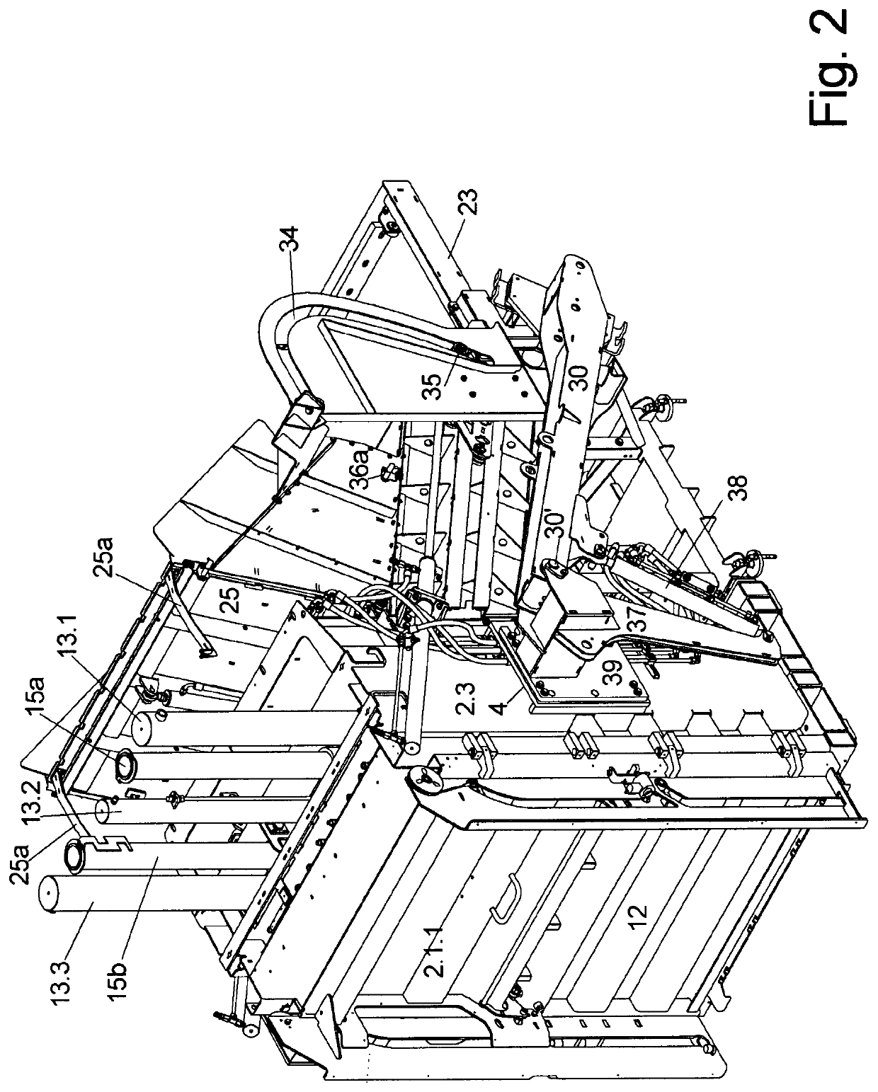
[0100]FIG. 2: a baler according to the invention with integrated lift-tilt device in perspective view,

[0101]FIG. 2a: the baler of FIG. 2 in side view, with the pivot arm approximately in the lower end position,

[0102]FIG. 2b: the baler in the position according to FIG. 2a in another side view with the viewing direction opposite to FIG. 2a,

[0103]FIG. 2c: the baler according to FIG. 2 in front view, i.e. looking at the removal door,

[0104]FIG. 2d: the baler according to FIG. 2 in top view with flap of the storage container open,

[0105]FIG. 3a: the baler of FIG. 2 in side view, with the pivot arm in a central pivot position,

[0106]FIG. 3b: the baler in the position according to FIG. 3a in another side view with the viewing direction opposite to FIG. 3a,

[0107]FIG. 4: a perspective view of the baler according to the previous figures, with the pivot arm approximately in the upper end position and a collector trolley suspended in the lift-tilt device,

[0108]FIG. 4a: a side view of the baler i...

second embodiment

[0153]FIG. 5 shows this second embodiment of a box baler 1, in which the lift-tilt device 22 could be integrated or installed on it, in which the essential difference compared to the first design of FIGS. 2 to 4 is that the bottom 21a of the storage container 21 runs horizontally.

[0154]Additionally, in FIG. 5, the cover flap 25 is shown swung up and open with its bottom 25b facing downward at an angle, as is necessary to allow goods M to fall from a storage container SW into the storage container 21.

[0155]The end wall 21e of the storage container 21 is vertical as in the 1st embodiment, and so is the storage slide 24 arranged therein, but the slide direction 24′ of the storage slide 24 is now horizontal.

[0156]The remaining construction of the baler 1 corresponds to that of the first embodiment of FIGS. 2 to 4.

[0157]Furthermore, in FIGS. 2a to 4a, the optional side plates 29a, b, which are best seen in FIG. 2a, are present in alignment with or parallel to the side walls 21c, d of the...


PUM


Abstract

In that the lifting and tilting device (22)—which can be used as a separate assembly or integrated in or on a baler (1) for lifting up and tilting out a collector trolley (SW)—consists of only one long pivot arm (30) and a tilting part (31) tiltably attached thereto, the tilting movement of which is controlled by a link guide (33), a very stable, structurally simple and purely mechanical device can be achieved, as well as a baler (1) equipped therewith.

Description

I. FIELD OF APPLICATION[0001]The invention relates to a lift-and-tilt device by means of which containers open at the top can be lifted up and emptied by tilting, usually into a filling opening located at a high levelII. TECHNICAL BACKGROUND[0002]A typical application for this are baling presses into which materials to be pressed, for example packaging materials such as cardboards, films or flattened beverage containers, must be fed via such a filling opening as a filling opening for the most automated feeding possible of such a baling press.[0003]For this purpose, lift-tilt devices are often used, into which a collector trolley open at the top and filled with the corresponding materials to be compressed is moved, which is then first brought to the height of the filling opening by means of this lift-tilt device and is emptied by tilting into the filling opening. The filling opening is generally located above the bale chamber of the baler, and thus—depending on its size—at or above h...

Claims


Application Information

Patent Timeline
IPC IPC(8): B30B9/30B65G67/04B65G67/30
CPCB30B9/301B65G67/30B65G67/04B30B9/3078B65F1/1452
Inventor SCHWELLING, HERMANN
Owner SCHWELLING HERMANN
Why Eureka
Try Eureka