
End barrier box and a reflow oven using the end barrier box

Pending Publication Date: 2021-12-02
ILLINOIS TOOL WORKS INC
View PDF0 Cites 0 Cited by
  • Summary
  • Abstract
  • Description
  • Claims
  • Application Information

AI Technical Summary

Benefits of technology

The present invention provides an end barrier box that is easy to disassemble and clean. The deflector has at least three fins, making it simple to remove without having to disassemble the rails. This makes maintenance and cleaning much more convenient.

Problems solved by technology

For a reflow oven that uses an inert gas as the working gas, if air from the external environment enters the hearth, the inert atmosphere in the hearth will be destroyed, resulting in difficulty in controlling the ratio of inert gas to oxygen gas and the gas temperature in the furnace.
However, during use of the end barrier box, the gas in the hearth of the reflow oven contacts the end barrier box, such that volatile contaminants in these gases form condensate on the internal components of the end barrier box.

Method used


Image

  • End barrier box and a reflow oven using the end barrier box
  • End barrier box and a reflow oven using the end barrier box
  • End barrier box and a reflow oven using the end barrier box

Examples


Embodiment Construction

[0022]Various specific embodiments of the present application will be described below with reference to the drawings which form a part of this specification. It should be understood that although terms referring to directions, such as “front”, “rear”, “upper”, “lower”, “left”, “right”, “top”, “bottom”, etc., are used in the present application to describe various exemplary structural parts and elements of the present application, these terms are used herein for illustrative purposes only, and are based on the exemplary orientations shown in the drawings. Since the embodiments disclosed in the present application may be arranged in different directions, these terms are merely illustrative and are not to be considered as limiting. Wherever possible, the same or similar reference numerals used in the present application are used to refer to the same components.

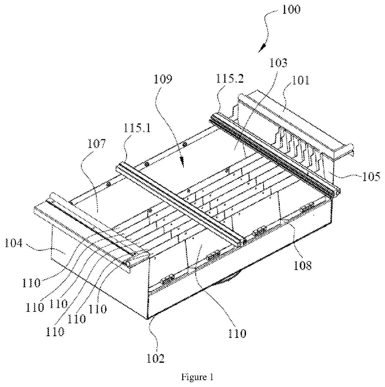
[0023]FIG. 1 is a three-dimensional structural view of an end barrier box 100 of the present application when assembled below g...


PUM

PropertyMeasurementUnit
Widthaaaaaaaaaa

Abstract

The present application discloses an end barrier box for blocking ambient gases from entering a hearth of a reflow oven, including: a box body, wherein the box body includes a bottom and a top, the bottom has a mounting bottom plate, the top has an opening, the box body further includes a pair of side walls, and the side walls are oppositely disposed; and a plurality of deflectors, wherein each of the plurality of deflectors is mounted between the pair of side walls, each of the plurality of deflectors includes at least three fins, and the at least three fins are mounted on the mounting bottom plate and extend upward from the mounting bottom plate. According to the end barrier box of the present application, the deflector is set to include at least three fins, so that the deflector can be easily disassembled without disassembling the rails, which is convenient for cleaning and maintenance of the end barrier box.

Description

FIELD OF THE INVENTION[0001]The present application relates to a reflow oven and an end barrier box used at an inlet end and an outlet end of the reflow oven.BACKGROUND OF THE INVENTION[0002]For a reflow oven that uses an inert gas as the working gas, if air from the external environment enters the hearth, the inert atmosphere in the hearth will be destroyed, resulting in difficulty in controlling the ratio of inert gas to oxygen gas and the gas temperature in the furnace. Therefore, the top and the bottom of the inlet end and the outlet end of the reflow oven are respectively provided with end barrier boxes with opposite openings, wherein the end barrier box at the bottom is located below the workpiece delivery guide rail of the reflow oven. The inert gas delivered into the barrier box can form a barrier region between the top and bottom end barrier boxes, thereby reducing air from the external environment going into the hearth of the reflow oven by means of a gas curtain.[0003]How...

Claims


Application Information

Patent Timeline
IPC IPC(8): F27B9/30F27D99/00B23K3/08B23K1/008
CPCF27B9/3011F27D99/0076B23K1/008B23K3/08F27D99/0075B23K3/00H05K3/34H05K3/3494F27B9/3005B23K1/012
Inventor WEI, DAOPENG
Owner ILLINOIS TOOL WORKS INC
Learn More