
Apparatus casing, projection system and assembling method of apparatus casing

Inactive Publication Date: 2013-06-13
CORETRONIC
View PDF5 Cites 0 Cited by
  • Summary
  • Abstract
  • Description
  • Claims
  • Application Information

AI Technical Summary

Benefits of technology

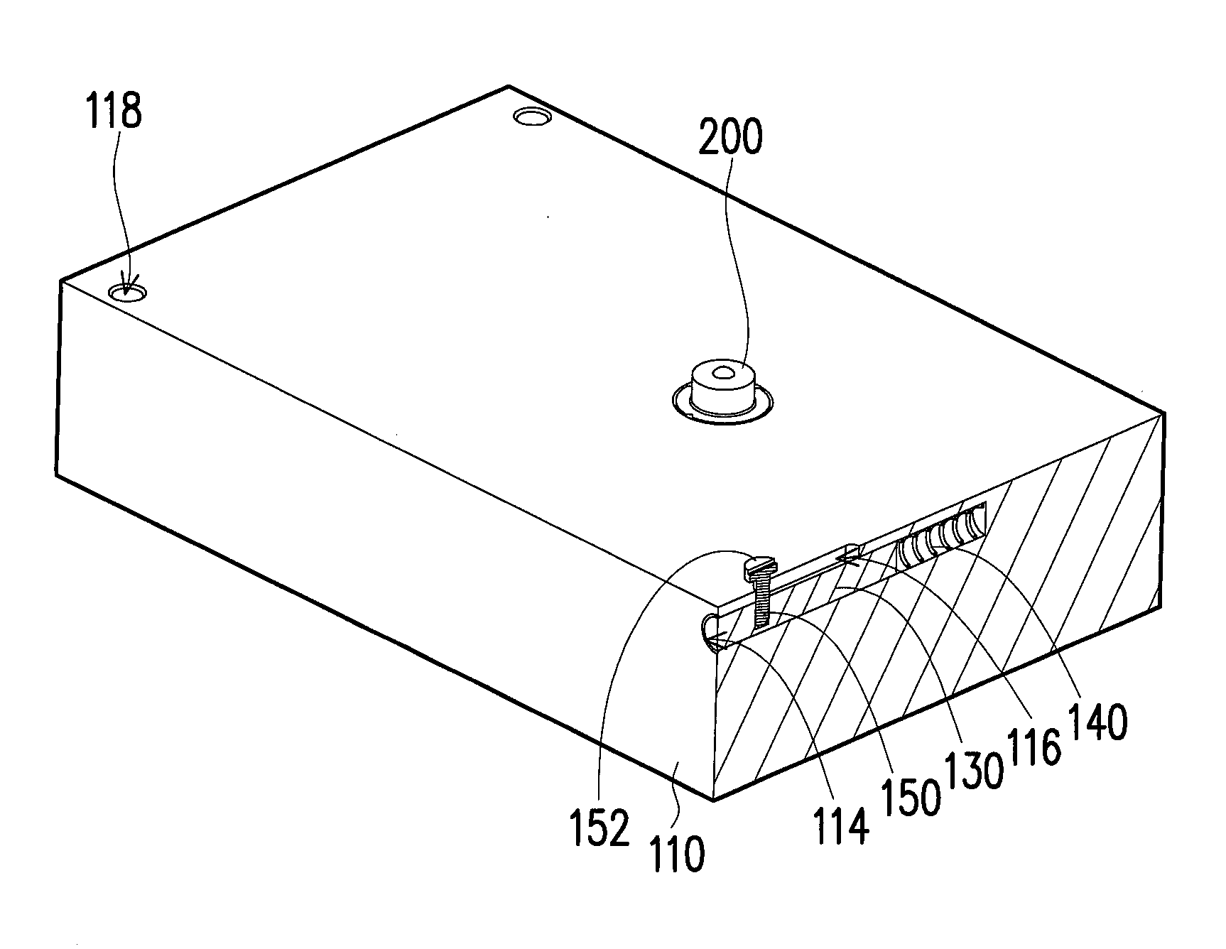
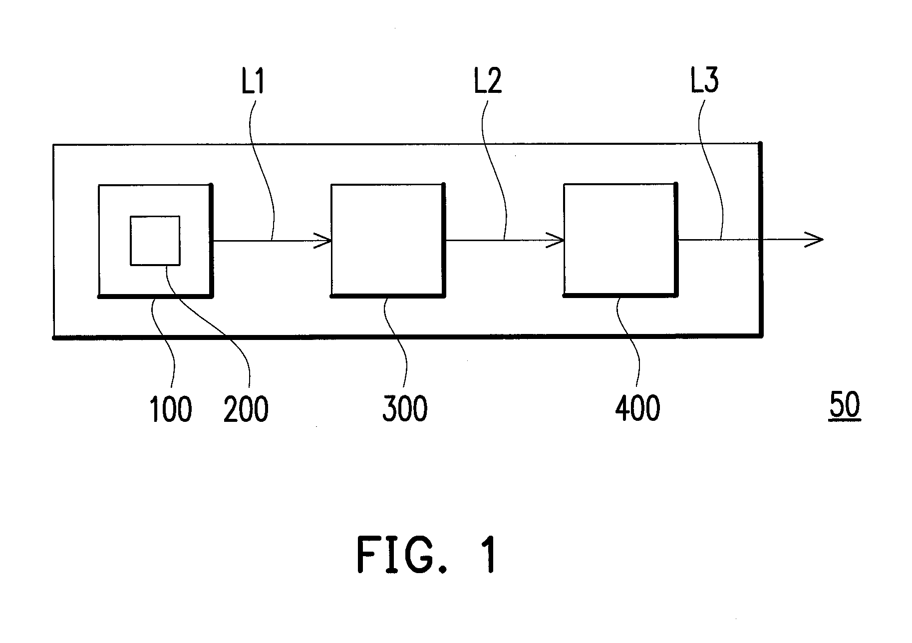
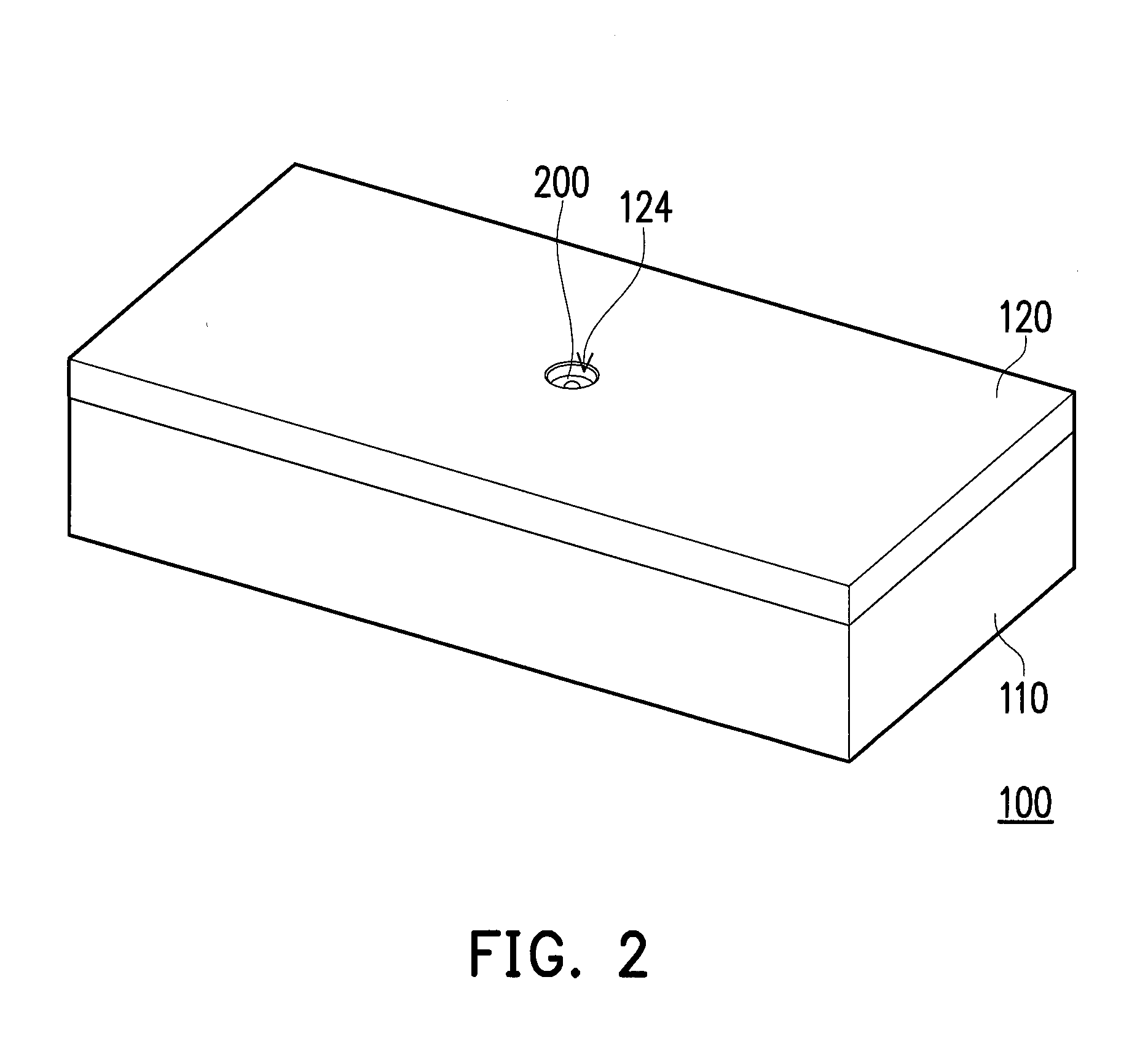
This patent is about a projection system that has a purpose-limiting mechanism to prevent the system from being disassembled easily. The system includes an apparatus casing that holds a laser light source, and the casing is designed to withstand external force and maintain its shape. The apparatus casing has a cavity and an open-hole, and a laser light source is placed in the cavity. A first shell has a cavity and an opening, and a second shell has a slot that aligns with a groove in the first shell. The groove and the first position-limiting part form a structural interference to limit the movement of the sliding part relatively to the first shell. This mechanism prevents the first shell and the second shell from separating easily, making it difficult for the system to be disassembled.

Problems solved by technology

In terms of the laser light source, the laser light source module of a projector available on the market could be easily detached by the user, which provides a loophole for a potential suspect to easily take away the laser light source for illegal purposes, and it may also injure the human body.

Method used


Image

  • Apparatus casing, projection system and assembling method of apparatus casing
  • Apparatus casing, projection system and assembling method of apparatus casing
  • Apparatus casing, projection system and assembling method of apparatus casing

Examples


Embodiment Construction

[0051]In the following detailed description of the preferred embodiments, reference is made to the accompanying drawings which form a part hereof, and in which are shown by way of illustration specific embodiments in which the invention may be practiced. In this regard, directional terminology, such as “top,”“bottom,”“front,”“back,” etc., is used with reference to the orientation of the Figure(s) being described. The components of the present invention can be positioned in a number of different orientations. As such, the directional terminology is used for purposes of illustration and is in no way limiting. On the other hand, the drawings are only schematic and the sizes of components may be exaggerated for clarity. It is to be understood that other embodiments may be utilized and structural changes may be made without departing from the scope of the present invention. Also, it is to be understood that the phraseology and terminology used herein are for the purpose of description an...


PUM

PropertyMeasurementUnit
Lengthaaaaaaaaaa
Forceaaaaaaaaaa
Diameteraaaaaaaaaa

Abstract

An apparatus casing including a first shell, a second shell covering the first shell, a sliding part, an elastic part and a position-limiting part is provided. The second shell has a slot. The slot includes two portions respectively having a first and a second width. The sliding part is slidably disposed in the first shell. The elastic part is compressed between the first shell and the sliding part. The position-limiting part is disposed at the sliding part. An end of the position-limiting part extends into the second shell through the slot. An external diameter of the end of the position-limiting part is greater than the first width but less than the second width. The sliding part withstands an elastic force generated by the elastic part to drive the end of the position-limiting part to move from a position of the first portion to a position of the second portion.

Description

CROSS-REFERENCE TO RELATED APPLICATION[0001]This application claims the priority benefit of China application serial no. 201110405764.5, filed on Dec. 8, 2011. The entirety of the above-mentioned patent application is hereby incorporated by reference herein and made a part of this specification.BACKGROUND OF THE INVENTION[0002]1. Field of the Invention[0003]The invention generally relates to an apparatus casing, a projection system and an assembling method of the apparatus casing, and more particularly, to an apparatus casing for installing and fixing a laser light source, a projection system using the apparatus casing and an assembling and disassembling method of the apparatus casing.[0004]2. Description of Related Art[0005]The projector is a display device for producing a large size frame and works based on an imaging principle of converting an illumination light-beam produced by a light source module into an image light-beam through a light valve and then, projecting the image li...

Claims


Application Information

Patent Timeline
IPC IPC(8): G03B21/20B23P17/04F21V15/01
CPCG03B21/145Y10T29/49895G03B21/2086G03B21/2033
Inventor LIU, KUANG-YAOLIU, I-HSIEN
Owner CORETRONIC
Learn More