Supercharge Your Innovation With Domain-Expert AI Agents!

Light field volumetric device for displaying fluctuating and stereoscopic 3D images flows and method thereof

a volumetric device and light field technology, applied in the direction of optics, instruments, electrical equipment, etc., can solve the problems of inconceivable display of this type, limitations affecting resolution capacity, playback speed, loss of brightness and light intensity, etc., and achieve the effect of not affecting the user

Inactive Publication Date: 2021-12-02
3D I V E SRL
View PDF0 Cites 0 Cited by
  • Summary
  • Abstract
  • Description
  • Claims
  • Application Information

AI Technical Summary

Benefits of technology

This patent is about a device that can create the visual effect of a three-dimensional image. It does this by measuring the areas of an image and adding a fluctuation to create a "virtual depth" that makes the image appear to fluctuate and be stereoscopic for the observer. This is made possible by using optical systems that can reproduce images at different points without needing waveguides or light pipes.

Problems solved by technology

In the past, the absence of a sufficiently developed background made the creation of displays of this type inconceivable.
In particular, depending on the technology used, volumetric 3D displays can present limitations affecting resolution capacity, the number of voxels, playback speed, loss of brightness and light intensity, the required use of vacuum chambers (which are costly and hazardous), the need to thermostat the system, a limited viewing angle, excessive proximity of the projected image to the device, limitations involving the display dimensions, scaling issues, possible blurring of image due to scattering phenomena, self-occlusion caused by the opacity of LED components and connection wires, and fabrication complexity.
Moreover, in many cases, it has been noted that such systems may be potentially hazardous to the eyes.
These systems are difficult to model and optimize, which leads to unpredictable results.
In addition, they do not make it possible to reproduce a natural stereoscopic view.
As a result, they have not proved to be sufficiently efficient, comfortable or tolerable by users to be produced on a large scale and used in daily life.

Method used


Image

  • Light field volumetric device for displaying fluctuating and stereoscopic 3D images flows and method thereof
  • Light field volumetric device for displaying fluctuating and stereoscopic 3D images flows and method thereof
  • Light field volumetric device for displaying fluctuating and stereoscopic 3D images flows and method thereof

Examples


second embodiment

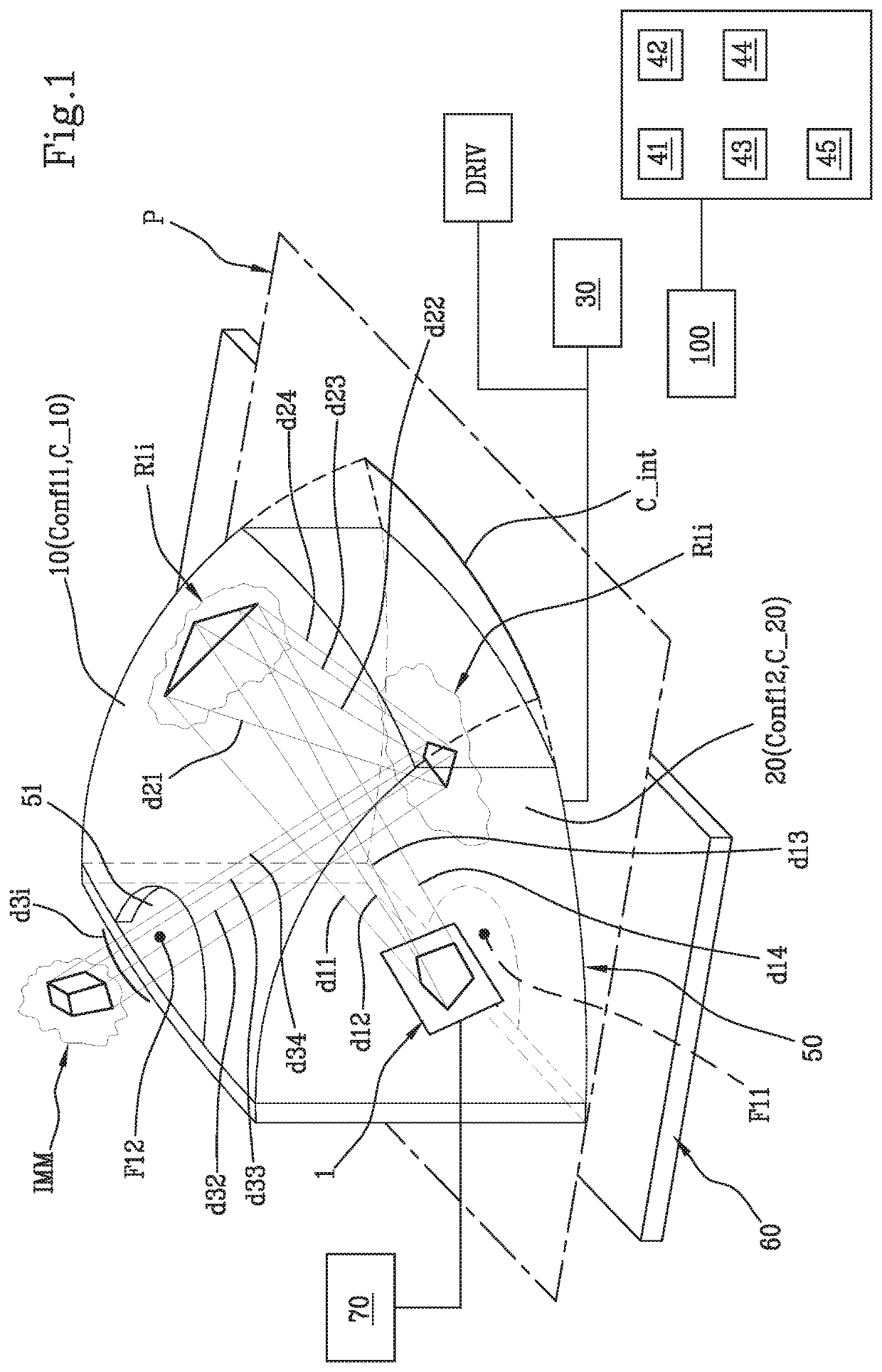
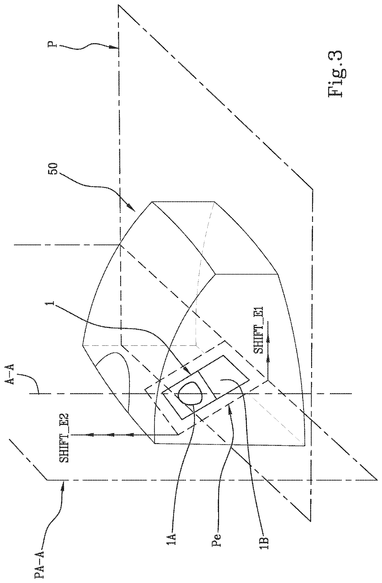
[0164]In particular, a first and the invention are shown in FIGS. 1 to 3 and in FIGS. 4 and 5, respectively, and in which the emitting means 1 are contained in the first reflection system 50 and in the second reflection system 150, respectively.

[0165]According to the invention, the emitting means 1 is offset with respect to the azimuth axis A-A of the reflection system 50, 150, as shall be described in further detail herein below.

[0166]The emitting means 1 is configured to transmit a beam of light rays R1i in first directions d1i.

[0167]In particular and referring specifically to FIG. 1, the first directions d1i comprise respective directions d11, d12, d13, d14 of light rays comprised in the beam.

[0168]According to the invention, the beam of light rays R1i represents a two-dimensional image flow.

[0169]The reflection system 50, 150 according to the invention comprises:

[0170]first concave reflecting means 10, 110 configured to receive the beam of light rays R1i and to reflect the beam...

first embodiment

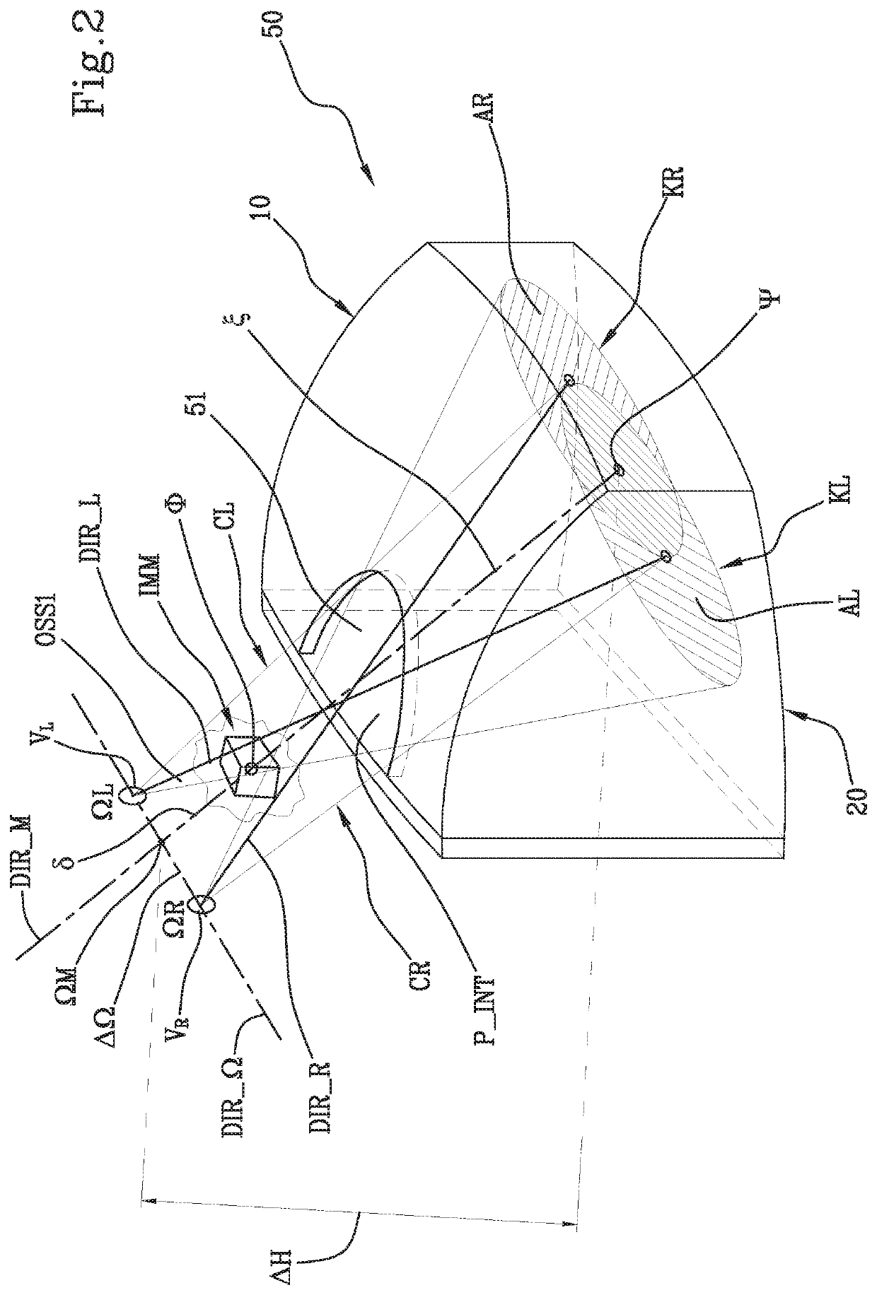
[0189]In the invention, particularly as shown in FIG. 1, the foci F11, F12 of the first concave reflecting means 10 and of the second concave reflecting means 20, respectively, lie on a straight line that defines the azimuth axis A-A of the first reflection system 50.

[0190]Referring particularly to FIG. 1, according to the invention the prolongations of the first concave reflecting means 10 and of the second concave reflecting means 20 intersect along an intersection curve C_int lying on a reference plane P perpendicular to the azimuth axis A-A of the reflection system 50.

[0191]In the second embodiment of the invention, as shown in FIGS. 4 and 5, second foci F21, F22 of the first concave reflecting means 110 and of the second concave reflecting means 120, respectively, lie on a straight line that defines the azimuth axis A-A of the second reflection system 150.

[0192]In this embodiment, the first concave reflecting means 110 and the second concave reflecting means 120 intersect along...


PUM


Abstract

A light field volumetric device for displaying images or flows of fluctuating and stereoscopic 3D images. The device includes emitting means and a reflection system. The reflection system has first and second concave reflecting means. The first concave reflecting means comprises an aperture. An image generated by the device is perceivable by an observer, located at a distance with respect to the second concave reflecting means, when the observer looks towards the second concave reflecting means. A calculation unit is associated with the device and is configured to calculate the distance.

Description

FIELD OF APPLICATION[0001]The object of the present invention is a light field volumetric device.[0002]In particular, the object of the invention is a light field volumetric device for displaying flows of fluctuating and stereoscopic 3D images.[0003]A method for displaying flows of fluctuating and stereoscopic images constitutes a further object of the invention.[0004]In other words, the object of the present invention is a device / method which enables flows of 3D images to be displayed, starting from 2D images, without requiring any display media.PRIOR ART[0005]One of today's major efforts at the scientific and technological level concerns the creation of 3D displays. In the past, the absence of a sufficiently developed background made the creation of displays of this type inconceivable. Today there are several options for creating 3D displays, which, however, involve some critical points. In particular, depending on the technology used, volumetric 3D displays can present limitation...

Claims


Application Information

Patent Timeline
Patent Type & Authority Applications(United States)
IPC IPC(8): G02B30/56G02B17/06G02B30/26H04N13/388
CPCG02B30/56H04N13/388G02B30/26G02B17/0621
Inventor BENASSI, ENRICOTREGNAGHI, GIOVANNILIBERATI, FABRIZIOMAUTINO, SARAROSSETTI, ANTO
Owner 3D I V E SRL
Features
  • R&D
  • Intellectual Property
  • Life Sciences
  • Materials
  • Tech Scout
  • Unparalleled Data Quality
  • Higher Quality Content
  • 60% Fewer Hallucinations
Learn More