Stator for an electric machine

a technology for electric machines and stabilizers, which is applied in the direction of windings conductors, shape/form/construction, etc., can solve the problems of affecting the adaptation of torque and power of electric machines to respective vehicles, and relatively high current displacement losses

Active Publication Date: 2021-12-02
ROBERT BOSCH GMBH
View PDF0 Cites 1 Cited by
  • Summary
  • Abstract
  • Description
  • Claims
  • Application Information

AI Technical Summary

Benefits of technology

The stator in this electric machine has a unique design that allows for more conductor elements per groove, which makes it easier to adjust the torque and power of the machine without changing its basic construction. This results in less current displacement losses and higher efficiency of the electric machine. Overall, this design allows for greater variability and flexibility in the number, width, and interconnection of conductor elements, achieving better performance and efficiency.

Problems solved by technology

This impedes the adaptation of the torque and of the power of the electric machine to the respective vehicles in which the electric machine is intended to be used.
Furthermore, this low number of conductor elements per groove leads to relatively high current displacement losses.

Method used


Image

  • Stator for an electric machine
  • Stator for an electric machine
  • Stator for an electric machine

Examples


Embodiment Construction

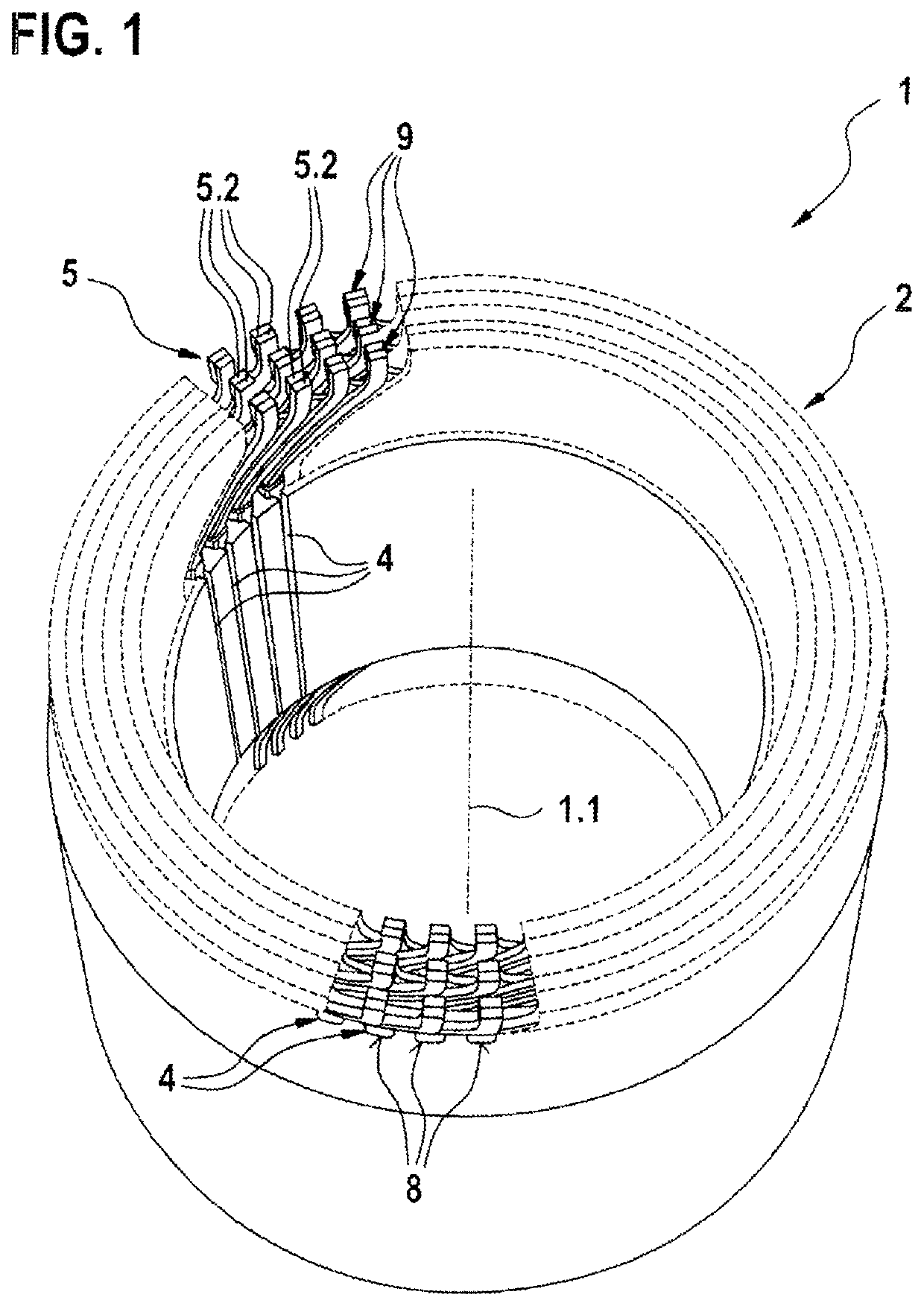
[0028]FIG. 1 shows a view of a stator of an electric machine with an insert winding according to the invention.

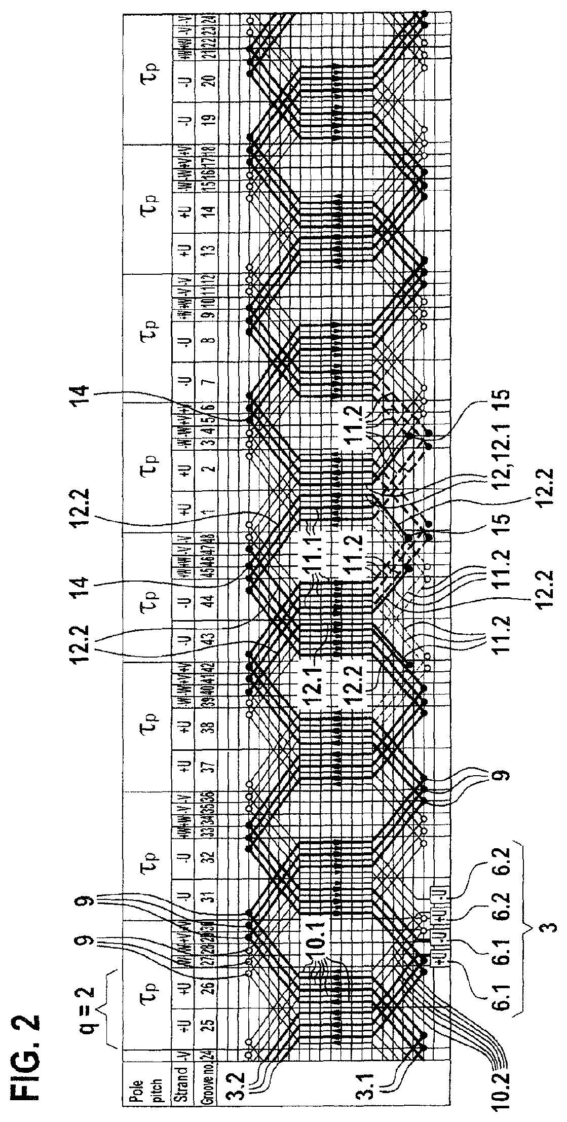
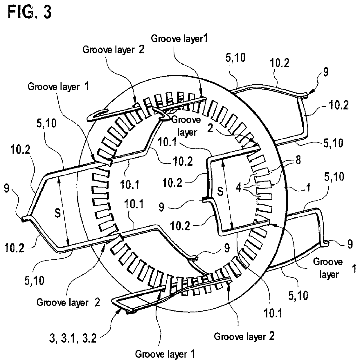
[0029]The stator 1 according to the invention of an electric machine has a polyphase winding 2 which is in the form of a so-called insert winding and which comprises winding strands 3 assigned to a particular electrical phase u, v, w. The winding strands 3 run in each case in undulating fashion through grooves 4 formed in the stator 1. The grooves 4 are arranged on the circumference of the stator 1 and run in each case in an axial direction with respect to a stator axis 1.1 of the stator 1. The winding strands 3 are formed in each case from different types of conductor elements 5. The polyphase winding 2 is designed so as to give rise to a particular number of holes q of, for example, equal to two. The individual conductor elements 5 of the polyphase winding 2 are arranged in their associated groove 4 in each case in a particular groove layer between a first or lowermost la...


PUM


Abstract

The invention relates to a stator having a multi-phase wave winding made of hairpin conductor elements (5). Each phase consists of two parallel or serially connected branches (6, 6.1, 6.2). Each branch has a first (3.1) and a second (3.2) winding portion, which are connected to each other in series. The slot position of the two limbs (5.1) of each hairpin conductor element alternates by +−1. The first winding portion (3.1) extends clockwise along the stator circumference; the second winding portion (3.2) extends counterclockwise and is connected to the first winding portion via a reverse-connector conductor element (12, 12.1, 12.2). Both limbs of the reverse-connector conductor element (12.1) of the first winding branch (6.1) are located in the uppermost slot position; the limbs of the reverse-connector conductor element (12.2) of the second winding branch (6.2) are located in the lowermost slot position.

Description

BACKGROUND OF THE INVENTION[0001]The invention proceeds from a stator for an electric machine.[0002]A stator for an electric machine is already known from DE 10 2013 225 130 A1, having a polyphase winding which is formed as an insert winding and which has winding strands assigned to a particular electrical phase, which winding strands run in each case in undulating fashion through grooves formed in the stator and are formed in each case from different types of conductor elements, wherein the conductor elements are arranged in the respective groove in a particular groove layer between a first or lowermost layer, facing toward a groove base, and an n-th or uppermost groove layer, averted from the groove base, wherein n corresponds to the number of conductor elements per groove and is an even number, wherein the conductor elements are in each case connected to one another by cohesive joining connections on both face sides of the stator. The grooves of the stator contain in each case on...

Claims


Application Information

Patent Timeline
Patent Type & Authority Applications(United States)
IPC IPC(8): H02K3/12H02K3/28
CPCH02K3/12H02K3/28
Inventor HERZBERGER, ANDREASELSER, ARMINERMER, MARTINHEUSER, PATRICKHEIN, TOBIASRIEDL, JOHANNES
Owner ROBERT BOSCH GMBH
Why Eureka
Try Eureka