Valve device in a motor vehicle

Inactive Publication Date: 2017-12-21
CONTINENTAL AUTOMOTIVE GMBH
View PDF8 Cites 0 Cited by
  • Summary
  • Abstract
  • Description
  • Claims
  • Application Information

AI Technical Summary

Benefits of technology

This patent relates to a valve device that requires a small amount of space in the flow channel, making the device easier and less expensive to design. The invention achieves this by reducing the diameter of the spindle in the flow channel and using a flap with a small thickness. Additionally, the patent provides a refinement that further reduces the required space by reducing the diameter of the spindle beyond the flap. This refinement also improves the sealing action of the device by allowing the use of seals with sealing lips, even if the spindle is in a slight oblique position.

Problems solved by technology

Due to the spatial extent of the sealing lip on the wall of the flow channel, the use of such seals in the case of a slight oblique position of the spindle was hitherto problematic.

Method used


Image

  • Valve device in a motor vehicle
  • Valve device in a motor vehicle

Examples


Embodiment Construction

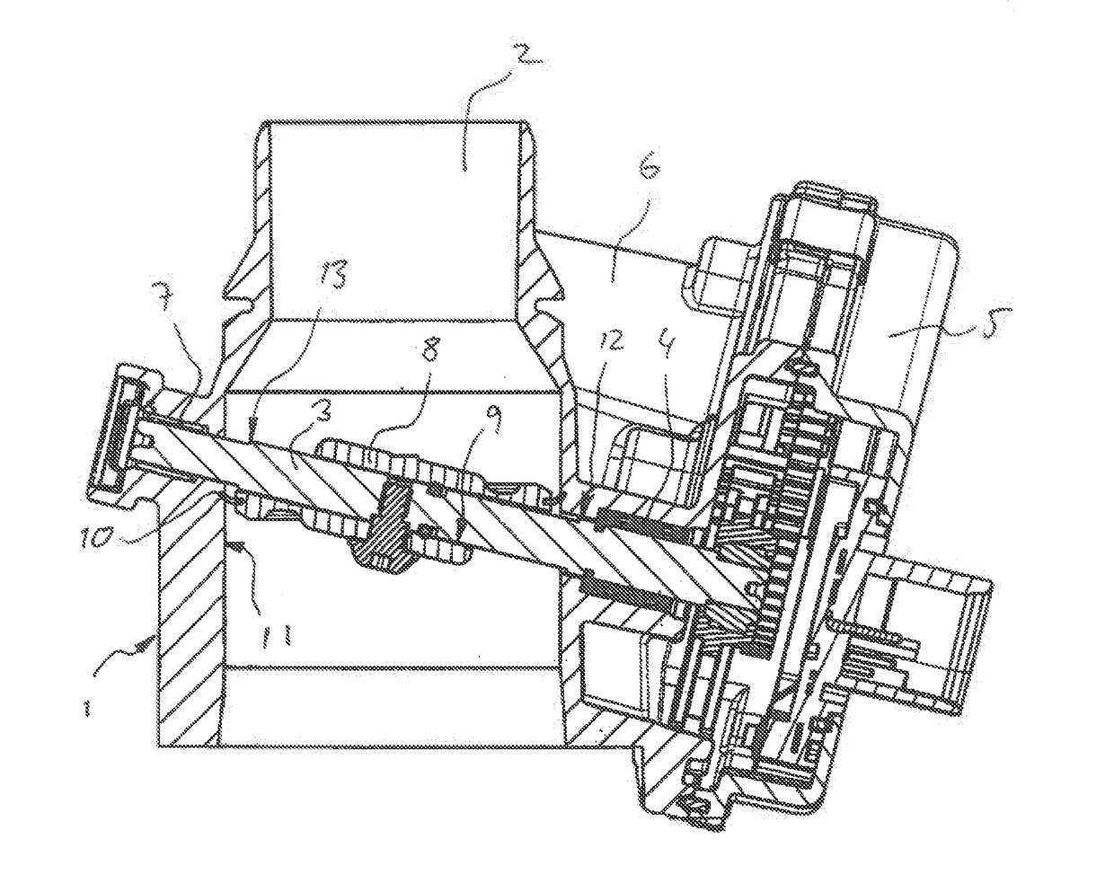
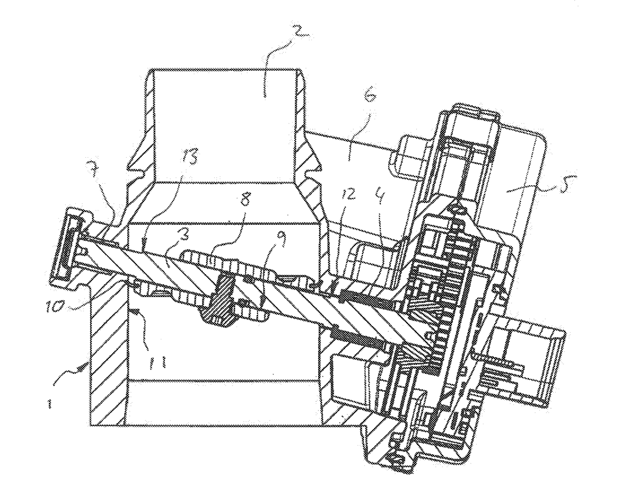
[0010]The valve device for a motor vehicle in the FIGURE includes a housing 1, having a flow channel 2, which is arranged in the housing and which serves for the through-flow of a fluid. In the present case, an air flow through the valve device is controlled. In the flow channel 2, there is arranged a spindle 3 mounted on both sides in the housing 1. A first bearing 4 is situated on that side of the housing 1 on which a gear mechanism 5 is arranged. The gear mechanism 5 is connected on the output side to the spindle 3, and on the input side to an electric motor (not shown) which is housed in a separate chamber 6 of the housing 1. A second bearing 7 for the spindle 3 is situated on that side of the flow channel 2 opposite to the gear mechanism 5. On the spindle 3, there is arranged a flap 8 that has a bore 9 through which the spindle 3 extends. The flap 8 is fastened on the spindle 3, by being screwed to the spindle 3. The flap 8 further has a radially circumferential edge on which t...


PUM


Abstract

A valve device in a motor vehicle including a housing; a flow passage arranged in the housing; a flap arranged in the flow passage for closing the flow passage, wherein the flap is secured on an axle, and the axle is rotatably mounted in the housing, and can be driven by an electric motor via a gear unit; and a valve seat arranged in the flow passage, with which valve seat the flap is in contact in a closing position, wherein the axle penetrates the flap at an angle. The part of the axle located in the flow passage has a smaller diameter than in the area of the bearing on the side of the gear unit.

Description

CROSS-REFERENCE TO RELATED APPLICATIONS[0001]This is a U.S. national stage of application No. PCT / EP2015 / 079823, filed on 15 Dec. 2015, which claims priority to the German Application No. 10 2014 226 732.3 filed 19 Dec. 2014, the content of both incorporated herein by reference.BACKGROUND OF THE INVENTION1. Field of the Invention[0002]The invention relates to a valve device in a motor vehicle, having a flow channel arranged in a housing. A flap is arranged in the flow channel and serves to close off the flow channel. The flap is fastened on a spindle and the spindle is mounted rotatably in the housing and can be driven by an electric motor via a gear mechanism. A valve seat is arranged in the flow channel. The flap is in contact with the valve seat in the closed position, the spindle penetrating the flap at an angle.2. Related Art[0003]Valve devices are used, for example, as throttle flap connectors for the air mass control of combustion engines or in fuel cell systems. Due to the p...

Claims


Application Information

Patent Timeline
IPC IPC(8): F16K1/22F16K31/04F02D9/10
CPCF16K1/224F02D9/1065F16K31/047
Inventor MONTIGNY, RAINER JOHANNESKOPP, STEFAN
Owner CONTINENTAL AUTOMOTIVE GMBH
Why Eureka
Try Eureka