Pumping unit

Inactive Publication Date: 2005-07-14
VOITH TURBO GMBH & CO KG
View PDF1 Cites 3 Cited by
  • Summary
  • Abstract
  • Description
  • Claims
  • Application Information

AI Technical Summary

Benefits of technology

[0014] Many advantages can be achieved or retained by the embodiment according to the invention, such as, for example, the relatively small structural space necessary for the pumping unit, the forming of the motor and the pump into one integral unit, the cooling of the motor by the pumping medium, which is particularly a hydraulic oil, the comparatively great reduction in sound level, as well as the possibility of being able to separately examine the two units, i.e., pump and motor. In particular, the pumping unit according to the invention is free of any radial packing rings, ventilating fan noise, roller bearings as well as special pump supports and elastic couplings.

Problems solved by technology

It has been determined, however, that in the case of specific pump data, for example, in the case of a small displaced volume and low pressure, the ratio of motor dimensions to pump dimensions is unfavorable.

Method used


Image

  • Pumping unit
  • Pumping unit
  • Pumping unit

Examples


Embodiment Construction

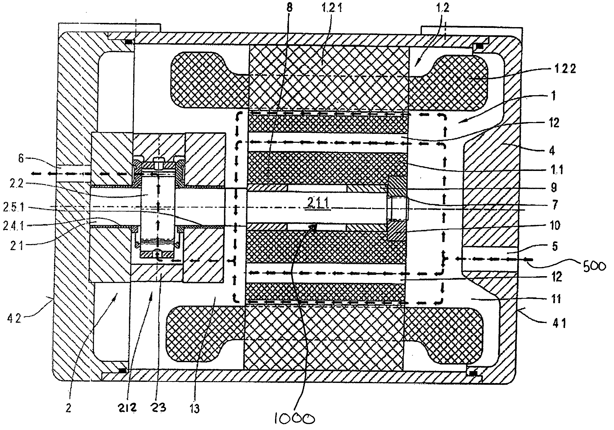
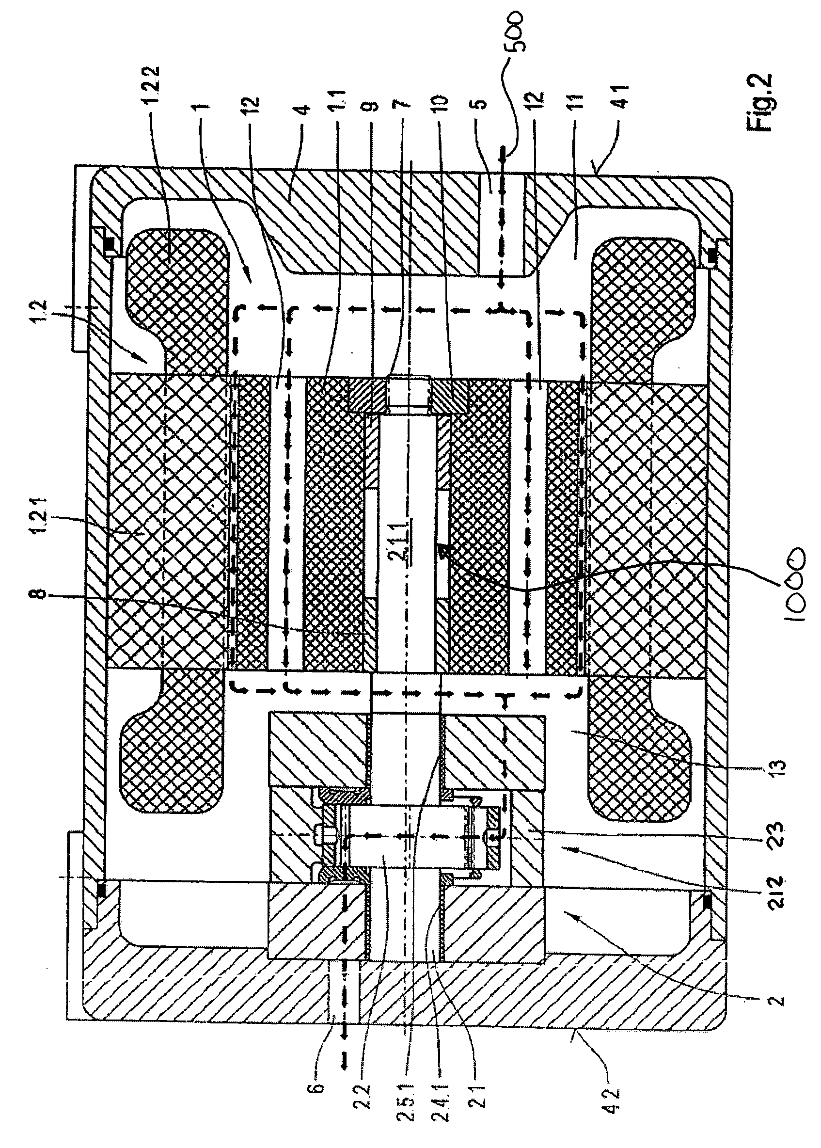
[0020] Referring to FIG. 2, pump 2 is no longer completely arranged inside stator 12 of electric motor 1, but rather only partly inside it, and in fact exclusively inside one axial end of the stator winding 122 and completely outside the axial region of the stator sheet stack 121.

[0021] The shaft 21 of pump 2 has two segments or regions, a first segment or region 211, which is allocated to the rotor 11 of the electric motor, and a second segment or region 212, which is allocated to the pump 2. The pump shaft 21 is mounted inside pump 2 in region 212, preferably by means of the friction bearings 241 and 251 on both sides of the pinion 22 borne by the pump shaft 21. The region 211 of the pump shaft 21, which is formed with a comparatively smaller diameter than the region 212, is completely enclosed by the rotor 11 (which is shaped like a hollow cylinder having a central bore 1000), and bears rotor 11, for example, by means of spacer pieces or spacer sleeves 8 and 9, which are shown. ...


PUM


Abstract

A pumping unit is provided with a pump that is partially disposed in a stator of an electric motor. The rotor is at an opposite end from the pump and is connected to the pump shaft to drive it for fluid flow. The pump shaft can be positioned in a central bore of the rotor and connected thereto via a meshing gear.

Description

RELATED APPLICATIONS [0001] This application claims priority to German Application No. DE 103 54 312.0, filed on Nov. 20, 2003, the disclosure of which is incorporated herein by reference. BACKGROUND OF THE INVENTION [0002] 1. Field of the Invention [0003] The invention concerns a pumping unit, which has a gear pump and an electric motor in a common housing. Such a pumping unit is also designated as a motor-driven pump or a motor-driven pumping unit. [0004] 2. Description of the Related Art [0005] A motor-driven pumping unit is described by German Application DE 100 15 139 A1, shown in FIG. 1, and the disclosure of which is incorporated herein by reference. [0006] The motor-driven pumping unit comprises an electric motor 1 with a rotor 11 and a stator 12. The stator 12 has a stator sheet stack 121 and a winding 122. Rotor 11 has a pot shape and is U-shaped, viewed in axial section. [0007] A pump 2 is disposed radially inside rotor 11 and stator 12. As can be seen, this pump 2 is com...

Claims


Application Information

Patent Timeline
IPC IPC(8): F04B17/03F04B53/08F04C11/00F04C15/00
CPCF04B17/03F04C15/008F04C11/008F04B53/08
Inventor ARBOGAST, FRANZ
Owner VOITH TURBO GMBH & CO KG
Why Eureka
Try Eureka