Auxiliary drive of a combustion machine

Active Publication Date: 2017-09-28
MAN NUTZFAHRZEUGE AG
View PDF1 Cites 1 Cited by
  • Summary
  • Abstract
  • Description
  • Claims
  • Application Information

AI Technical Summary

Benefits of technology

The present patent aims to provide a better arrangement of auxiliary assemblies in a combustion machine. The new arrangement takes up less space and allows for easy modification of the machine for additional auxiliary assemblies. The shaft can be mounted using a separate intermediate case or in a case section of the crankcase or control case, with radial and axial bearings to reduce or eliminate normally service-life-limiting forces. The intermediate case can also serve as a control case and protect the shaft from fouling and damage. The technical effects of the invention are improved performance and durability of the combustion machine, reduced space requirement, flexibility, and improved efficiency.

Problems solved by technology

The greater the number of auxiliary assemblies provided in a vehicle, the more difficult it becomes in spatial terms for these to be fastened in a suitable manner to the vehicle engine, and the more cumbersome and complicated the required drives become.
Such a multiplicity of auxiliary assemblies and belt drives or the like poses difficulties not only owing to the engine bay, which nowadays is generally of very tight dimensions.
Problems however arise in the case of equipment with further auxiliary assemblies, for example if the utility vehicle is to be equipped with a system for waste heat recovery (WHR), in the case of which, for example, it is sought to use an expansion machine.

Method used


Image

  • Auxiliary drive of a combustion machine
  • Auxiliary drive of a combustion machine
  • Auxiliary drive of a combustion machine

Examples


Embodiment Construction

[0043]Identical or functionally equivalent elements are denoted by the same reference designations throughout the figures.

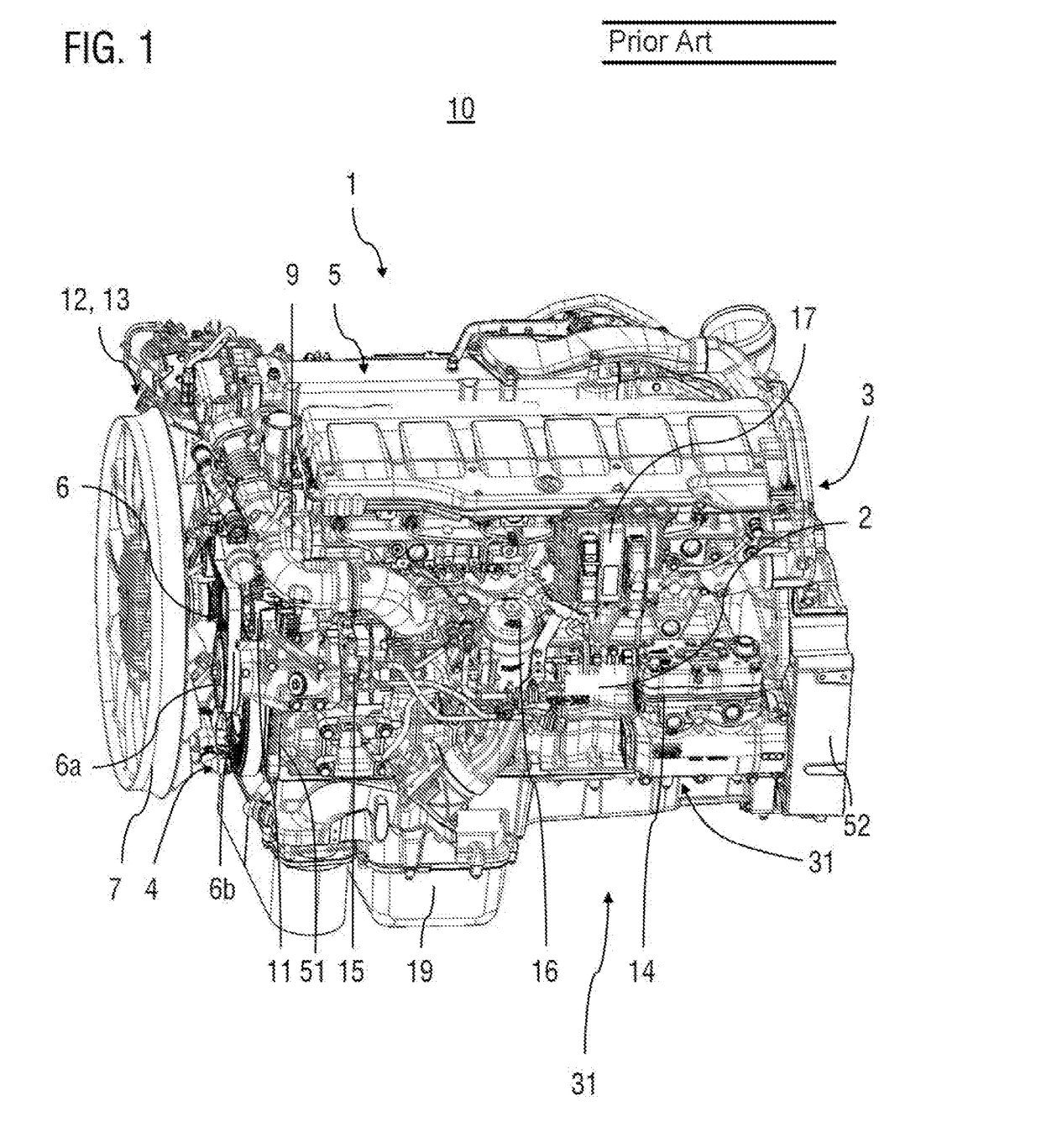
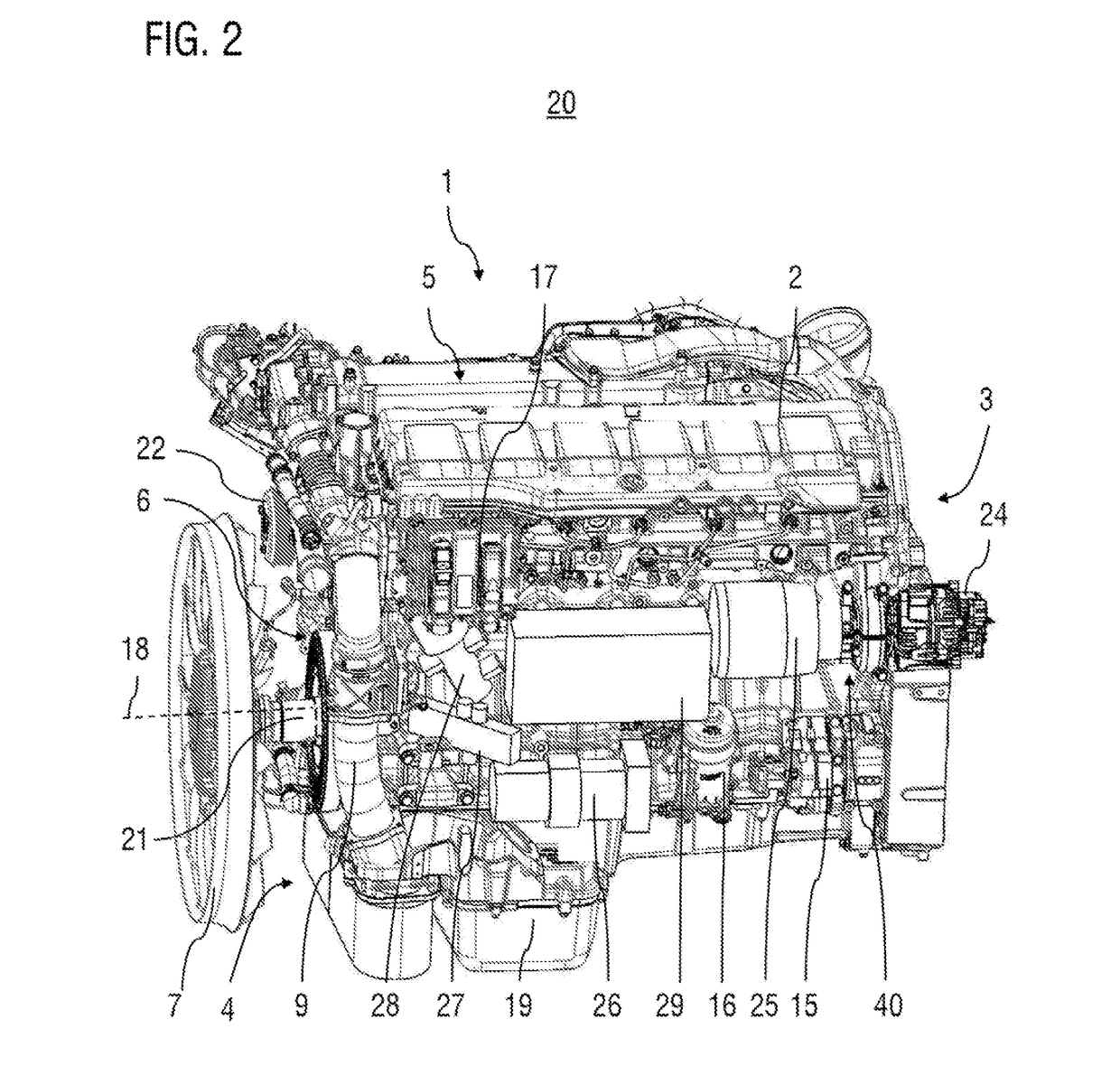
[0044]FIG. 2 shows a perspective view of an arrangement 20 of auxiliary assemblies on an internal combustion engine 1 of a utility vehicle as per an exemplary embodiment of the present disclosure. The internal combustion engine 1 is in the form of a diesel combustion machine. The top side of the internal combustion engine 1 is, as in FIG. 1, denoted by the reference designation 5, the front face side is denoted by the reference designation 4, and the rear, gearbox-side face side is denoted by the reference designation 3. The illustrated arrangement 20 of auxiliary assemblies is formed without a belt drive, that is to say so as to be free of a belt drive. The front gear drive has also been omitted in relation to the arrangement shown in FIG. 1.

[0045]By way of example, proceeding from the known arrangement illustrated in FIG. 1, the omission of the belt drive has b...


PUM


Abstract

The present disclosure relates to an auxiliary drive of a combustion machine, in particular of a combustion machine of a utility vehicle. The auxiliary drive includes a shaft which is operatively connected to a crankshaft of the combustion machine and which has two shaft ends which are designed in each case for connection to a power-outputting and / or power-receiving machine arranged outside the crankcase.

Description

BACKGROUND[0001]1. Technical Field[0002]The present disclosure relates to an auxiliary drive of a combustion machine, in particular of a combustion machine of a utility vehicle.[0003]2. Description of Related Art[0004]Combustion machines of utility vehicles often have a power take-off which serves for the drive of appliances or auxiliary assemblies. For this purpose, it is known for a shaft of the auxiliary drive to be driven by a crankshaft of the combustion machine via intermediate gears. For example, the laid-open specification EP 1 174 605 A2 has disclosed for example an auxiliary drive of a combustion machine comprising a shaft which is guided in a case by way of radial and axial bearings and which is connected rotationally conjointly to a gearwheel, wherein said gearwheel can be driven by a crankshaft of the combustion machine via intermediate gears, and the shaft, at its free end, has a drive-output flange, which is connected rotationally conjointly to the shaft, for the purp...

Claims


Application Information

Patent Timeline
IPC IPC(8): B60K25/02B60K17/28F02B67/04B60K6/40
CPCB60K25/02B60K6/40B60K17/28B60Y2400/795B60K2025/022B60Y2410/102F02B67/04F02B41/10F02G5/04F02B67/00Y02T10/12
Inventor RAAB, GOTTFRIEDKLAMMER, JOSEFHUNDSBERGER, EWALD
Owner MAN NUTZFAHRZEUGE AG
Why Eureka
Try Eureka