Submarine power cable

a technology of submarine power cable and insulated conductor, which is applied in the direction of power cables, cables, insulated conductors, etc., can solve the problems of affecting the electrical properties of submarine power cables, difficulty in knowing how far water and/or moisture will penetrate the conductor, and short spare cables

Pending Publication Date: 2021-12-09
NEXANS
View PDF3 Cites 0 Cited by
  • Summary
  • Abstract
  • Description
  • Claims
  • Application Information

AI Technical Summary

Benefits of technology

[0032]In one aspect, the area of each stranded conductor which is compressed may have a length between 1-1500 mm, more preferably a length between 10-1000 mm, even more preferably a length between 15-850 mm.
[0033]If the matrixes or dies used with the compression tool have a length (or width) that is smaller than the intended length of the area which is to be compressed, the compression may be done in several steps. The matrixes or dies will then be arranged around the outer circumference of the stranded conductor and the compression tool is used to compress a first part of the compression, whereafter the matrixes or dies are released and moved in the longitudinal direction of the stranded conductor to compress a subsequent part of the compression. This process will be repeated until the length of the compression is obtained. Thereafter the same is repeated for each area which is to be compressed in order to provide a watertight partition.

Problems solved by technology

If such an insulation system is damaged, water or moisture may penetrate into the submarine cable over larger sections of the submarine power cable and thus disrupt the electrical properties of the submarine power cable.
If the damaged cable is wet for a long distance the spare cable might be too short.
In general, it is challenging to know how far water and / or moisture will penetrate the conductor at different pressures.

Method used


Image

  • Submarine power cable
  • Submarine power cable

Examples


Embodiment Construction

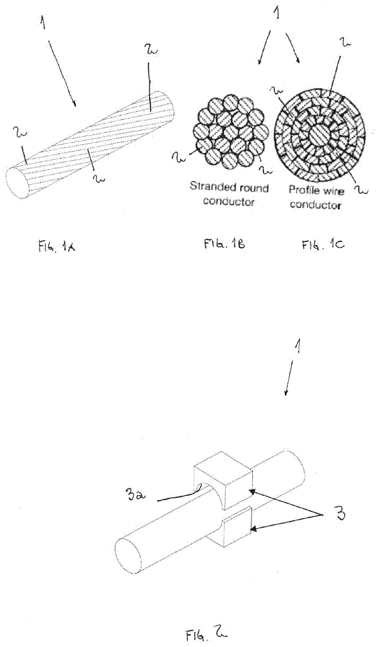
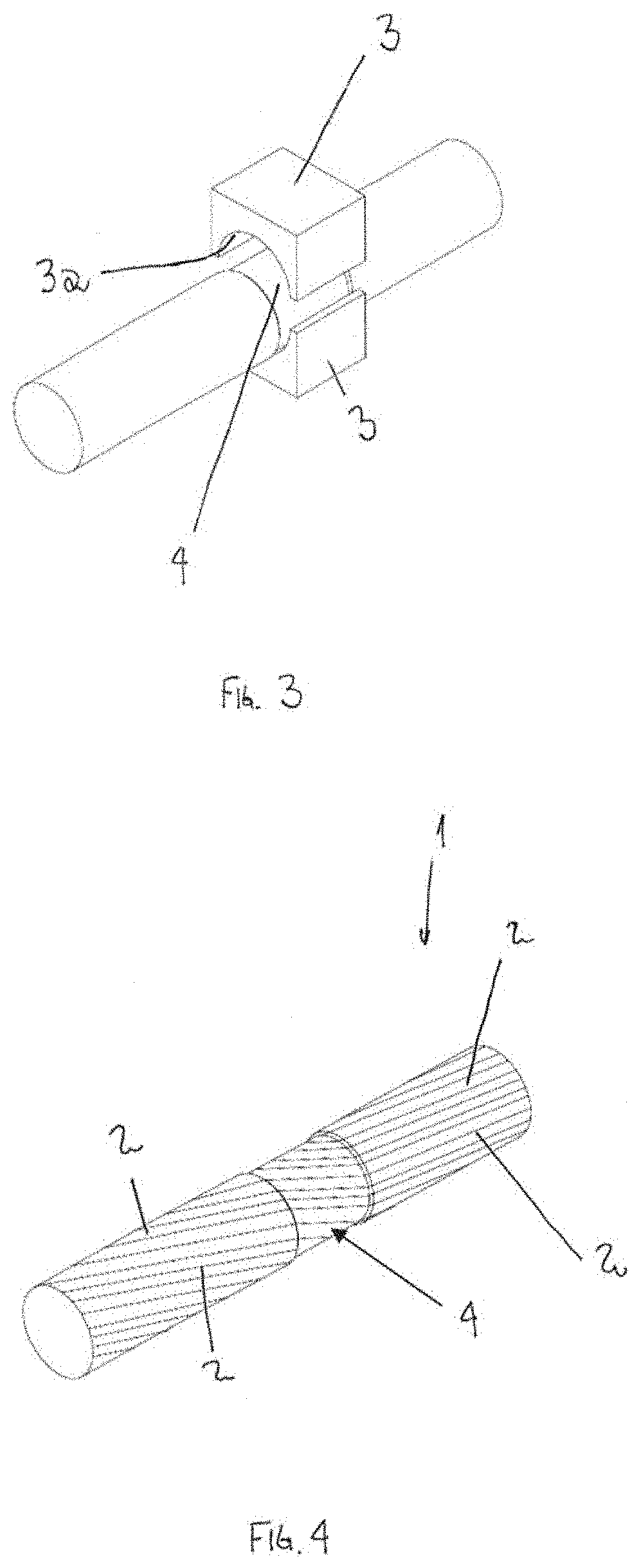
[0051]FIGS. 1A-1C illustrate different embodiments of a stranded conductor 1 of a submersible power cable according to the present invention, where FIG. 1A shows the stranded conductor 1 in a perspective view, while FIGS. 1B-1C show the stranded conductor 1 in a cross-sectional view.

[0052]The stranded conductor 1 comprises a plurality of metallic wires 2, where the metallic wires 2 are bundled or wrapped together to form the stranded conductor 1.

[0053]The plurality of metallic wires 2 of the stranded conductor 1 may be arranged together in a variety of configurations, for instance in a bunch stranding, a concentric stranding, an unilay stranding or a rope lay stranding. A person skilled in the art would know how this can be done, whereby this is not described any further herein.

[0054]It can also be seen from FIGS. 1B and 1C that the metallic wires 2 of the stranded conductor 1 may have different profile or cross-section.

[0055]The plurality of metallic wires 2 are made of aluminium, ...


PUM

PropertyMeasurementUnit
lengthaaaaaaaaaa
lengthaaaaaaaaaa
lengthaaaaaaaaaa

Abstract

A submarine power cable is provided having stranded conductor(s) and an insulation system, each individual stranded conductor, at given intervals, being compressed across an area to form a plurality of watertight partitions along a length of the of the submarine power cable. A method provides a plurality of watertight partitions along a length of the submarine power cable. The method includes, at a given point, arranging a compression tool around an outer circumference of the stranded conductor, using the compression tool to compress the stranded conductor, releasing the compression tool from the stranded conductor, and repeating the compression at a number of different points and using the compression tool to compress the stranded conductor at each of these points, thereby forming a plurality of watertight partitions along the length of the submarine power cable.

Description

RELATED APPLICATION[0001]This application claims the benefit of priority from European Patent Application No. 20 305 601.5, filed on Jun. 5, 2020, the entirety of which is incorporated by reference.FIELD OF THE INVENTION[0002]The present invention relates to a submarine power cable comprising at least one conductor part. In particular, the present invention relates to a watertight conductor part and a method for manufacturing of the watertight conductor part.BACKGROUND OF THE INVENTION[0003]Electric cables are used to transport electricity. This may range from large submarine power cables operating at high voltage and medium voltage to small home cable, including distribution cables. All power cables include a conductive core.[0004]Also, for larger cables, such as high voltage and medium voltage distribution cables and submarine cables, the cable may include a sheath configured to provide a water barrier to protect the insulated core. The sheath may also have a wire layer wound on t...

Claims


Application Information

Patent Timeline
Patent Type & Authority Applications(United States)
IPC IPC(8): H01B7/14H01B7/02H01B7/285H01B9/00H01B13/00
CPCH01B7/14H01B7/0225H01B13/0036H01B7/285H01B9/00H01B7/0291H01B7/0009H01B13/0006H01B7/2825Y02A30/14
Inventor ROD, ALF ERIK
Owner NEXANS
Why Eureka
Try Eureka