
Laser emitting system

Pending Publication Date: 2021-12-09
CHENGDU SUPERXON COMM TECH CO LTD
View PDF0 Cites 0 Cited by
  • Summary
  • Abstract
  • Description
  • Claims
  • Application Information

AI Technical Summary

Benefits of technology

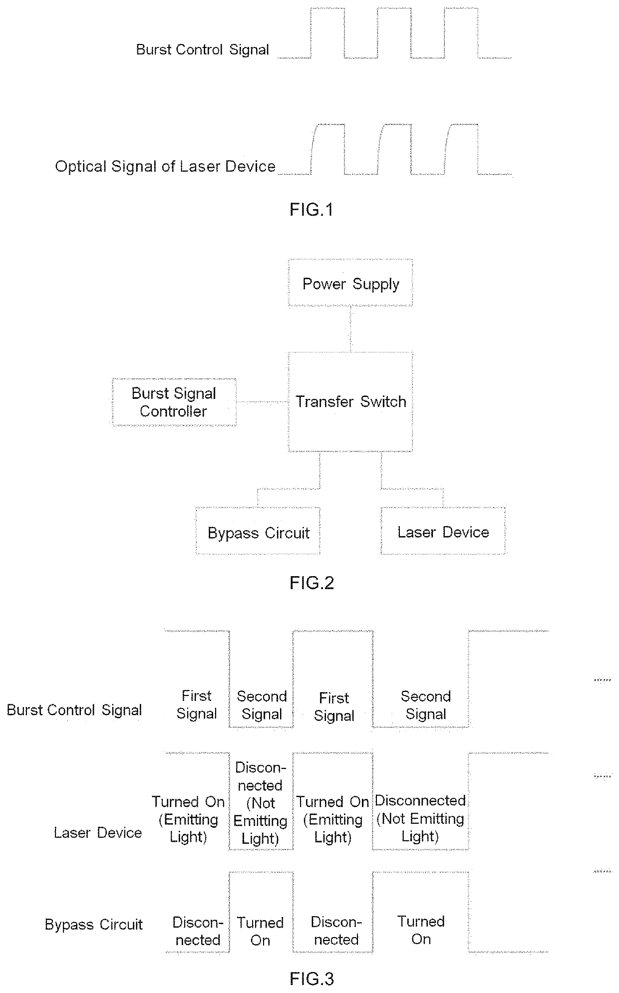
The present invention provides a laser system that can quickly establish the optical signal of the laser compared to previous methods.

Problems solved by technology

In addition, the laser device itself may also have stray capacitances.

Method used


Image

  • Laser emitting system
  • Laser emitting system
  • Laser emitting system

Examples


Embodiment Construction

[0031]The technical solutions in the embodiments of the present disclosure will be clearly and completely described below with reference to the drawings of the embodiments of the present disclosure. Apparently, the embodiments described are only some of the embodiments of the present disclosure, rather than all of the embodiments of the present disclosure. All the other embodiments that are obtained by a person skilled in the art on the basis of the embodiments of the present disclosure without inventive effort shall be covered by the protection scope of the present disclosure.

[0032]The terms “first”, “second”, “third”, “fourth”, etc., if present, in the description and claims of the present disclosure and in the above-described drawings are used to distinguish between similar objects, rather than necessarily describe a particular order or sequence. It should be understood that the data so used may be interchanged as appropriate, so that the embodiments described herein can be imple...


PUM


Abstract

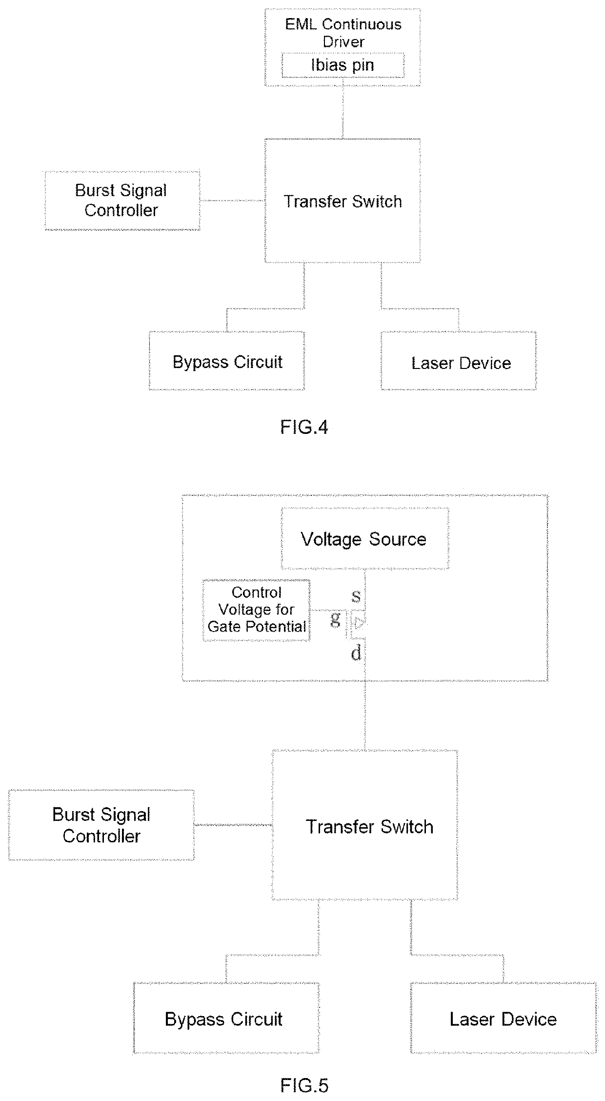
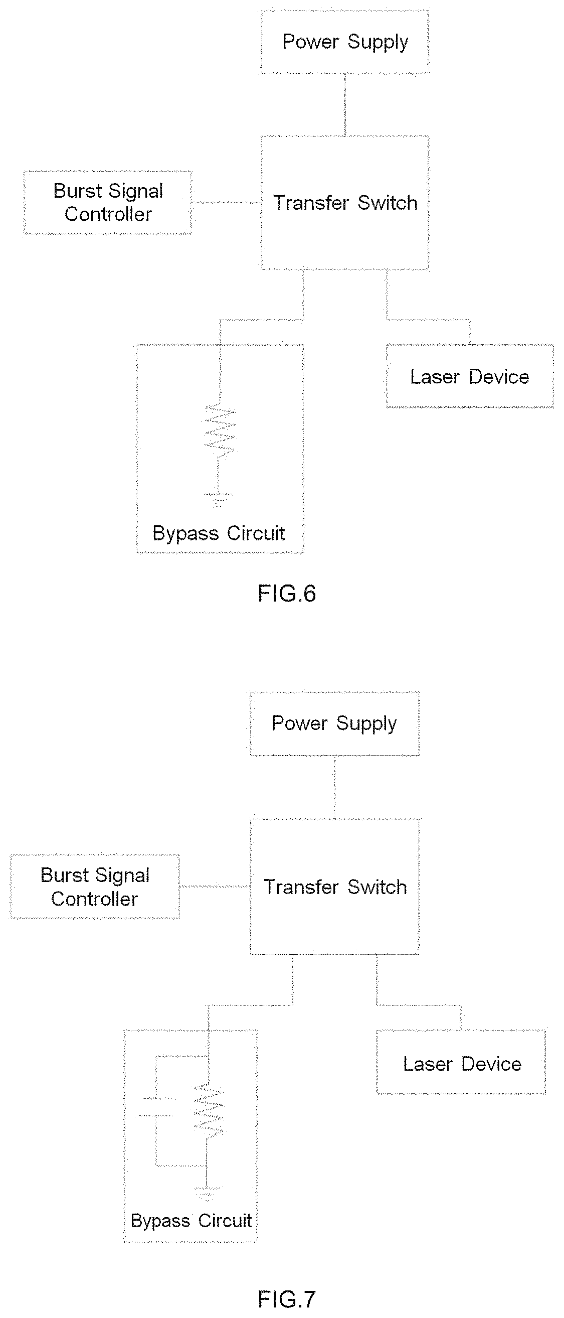
The present disclosure relates to the technical field of optical communication, and particularly to a laser emitting system, including a burst signal controller, a transfer switch, a power supply, a laser device and a bypass circuit, the burst signal controller is connected with the transfer switch and used for sending a burst control signal to the transfer switch, and the transfer switch is used for connecting the power supply to the laser device or the bypass circuit according to the burst control signal. The establishment time of an optical signal of a laser device can be shortened by using the laser emitting system of the present disclosure.

Description

CROSS-REFERENCE TO RELATED APPLICATIONS[0001]The present disclosure claims the priority of the Chinese patent application No. 201811259597.6, filed with the Chinese Patent Office on Oct. 26, 2018 and entitled “Laser Emitting System”, the contents of which is incorporated herein by reference in their entirety.TECHNICAL FIELD[0002]The present disclosure relates to the technical field of optical communication, and particularly to a laser emitting system.BACKGROUND ART[0003]With a rapidly increasing demand for information transmission bandwidth, in order to be able to meet the demand for larger capacity, TWDM-PON (Time and Wavelength Division Multiplexed Passive Optical Network) and NGPON2 (Next Generation Passive Optical Network stage 2) are proposed. Each optical line terminal in the PON system is connected with a plurality of ONUs (Optical Network Unit).[0004]As a light source device, a laser device is an essential constitution part of an ONU. In order to suppress performance degrada...

Claims


Application Information

Patent Timeline
IPC IPC(8): H04B10/50G02F1/025H01S5/125H01S5/06
CPCH04B10/5051H04B10/50595H01S5/0601H01S5/125G02F1/025H04B10/503H01S5/06825H01S5/0428H01S5/06216H01S5/12
Inventor LI, HAIYUAN
Owner CHENGDU SUPERXON COMM TECH CO LTD
Learn More