
Pressure sensor device and method for producing a pressure sensor device

a pressure sensor and pressure sensor technology, applied in the direction of measurement devices, fluid pressure measurement, instruments, etc., can solve the problems of reducing the possible stroke of the relevant sensing membrane, undesirable local bimetal effects, and negative effect on so as to improve the sensing capacity of the pressure sensor and improve the pressure sensor. , the effect of improving the pressure sensor

Active Publication Date: 2021-12-16
ROBERT BOSCH GMBH
View PDF0 Cites 0 Cited by
  • Summary
  • Abstract
  • Description
  • Claims
  • Application Information

AI Technical Summary

Benefits of technology

The present invention provides an improved pressure sensor device with reduced global bemetal effects, simple and robust design, and low cost of production. The electrode is directly or indirectly spring-mounted in the reference pressure chamber, and a layer of sacrificial material can increase its stiffness. The pressure sensor device has advantages over conventional devices, including smaller size, insensitive to bending / torsion, low temperature offset, and higher resonance frequencies, making it more susceptible to vibrations.

Problems solved by technology

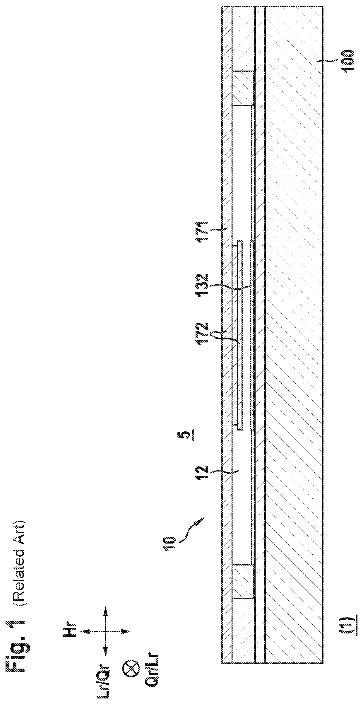
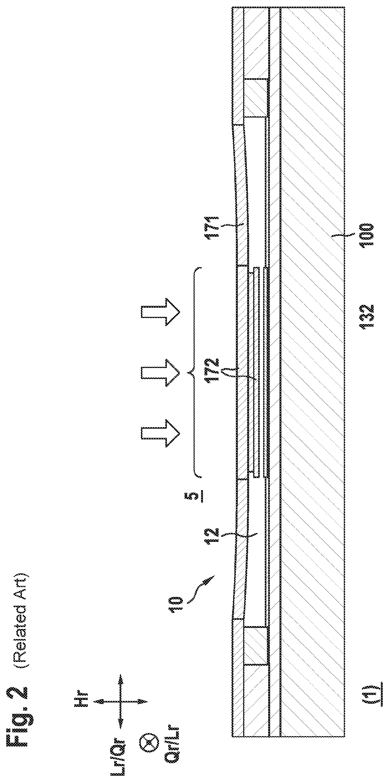
In conventional pressure sensors, it is disadvantageous (see also the description relating to FIGS. 1, 2, and 5), that in each case many small pressure sensor elements have to be combined to form a larger pressure sensor device for a pressure sensor in order to make it possible to counter a so-called global bimetal effect (stress from outside; see FIG. 5) of the pressure sensor.
Furthermore, in this way a possible stroke of the relevant sensing membranes is reduced, which has a negative effect on the sensing capacity of the pressure sensor.
Furthermore, different materials in the sealing regions of the sensing membranes result in undesirable local bimetal effects of the pressure sensors (internal stress).
The pressure sensor device is insensitive in particular to bending / torsion.

Method used


Image

  • Pressure sensor device and method for producing a pressure sensor device
  • Pressure sensor device and method for producing a pressure sensor device
  • Pressure sensor device and method for producing a pressure sensor device

Examples


Embodiment Construction

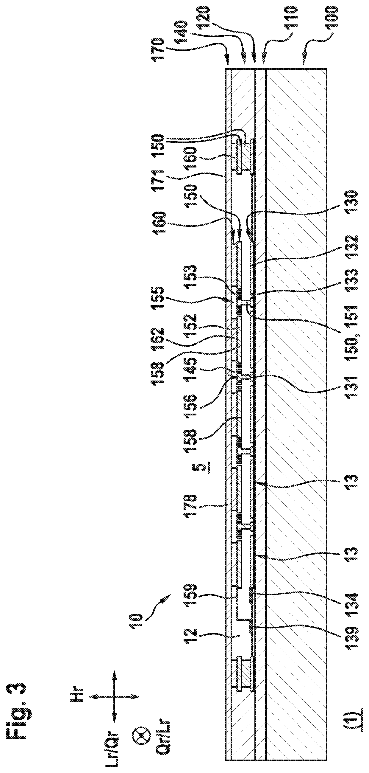
[0040]In the figures, only those spatial segments of an object of the present invention are shown that are necessary for an understanding of the present invention. In the following, the explanation of the present invention relates to (coordinate system) a longitudinal direction Lr or longitudinal axis Lr (both longitudinal directions, length), a transverse direction Qr or transverse axis Qr (both transverse directions, width), and a vertical direction Hr or vertical axis Hr (both vertical directions, thickness) of a specific embodiment of a pressure sensor device for a pressure sensor according to the present invention. A longitudinal direction Lr and a relevant transverse direction Qr can here constitute a diameter. Designations such as sensor and detector, sensing membrane and electrode, etc., are to be interpreted as synonymous, i.e., exchangeable with one another in each case when appropriate.

[0041]Below, the present invention is explained in more detail on the basis of exemplar...


PUM

PropertyMeasurementUnit
angleaaaaaaaaaa
angleaaaaaaaaaa
pressureaaaaaaaaaa

Abstract

A pressure sensor device for a pressure sensor, in particular a capacitive pressure sensor, having a pressure chamber bounded by a movable sensing membrane and a stationary counterelectrode of the pressure sensor device. The sensing membrane and the counterelectrode each run in the longitudinal direction and the transverse direction of the pressure sensor device. The sensing membrane is directly or indirectly spring-mounted, in particular spring-mounted in two-dimensional fashion, in the pressure chamber relative to the counterelectrode by at least one micromechanical spring element, in particular a plurality of micromechanical spring elements.

Description

FIELD[0001]The present invention relates to a pressure sensor device for a pressure sensor, in particular a capacitive pressure sensor. In addition, the present invention relates to a method for producing a pressure sensor device, in particular a capacitive pressure sensor device. In addition, the present invention relates to a pressure sensor, in particular a capacitive pressure sensor, as well as to an entity having such a pressure sensor device or such a pressure sensor.BACKGROUND INFORMATION[0002]Some convention capacitive pressure sensor devices, or capacitive pressure sensors, have pressure sensor devices in which a bending of a movable sensing membrane as electrode, or an electrode, can be determined based on a fluid pressure difference that has arisen, via a change of an electrical capacitance of the movable electrode relative to a counterelectrode situated opposite the sensing membrane.[0003]In such pressure sensor devices, for example a polysilicon membrane is situated opp...

Claims


Application Information

Patent Timeline
Patent Type & Authority Applications(United States)
IPC IPC(8): G01L9/00
CPCG01L9/0072G01L9/0042
Inventor REINMUTH, JOCHEN
Owner ROBERT BOSCH GMBH
Learn More