Sample holder unit for single-crystal x-ray structure analysis apparatus

Pending Publication Date: 2021-12-23
RIGAKU CORP
0 Cites 0 Cited by

AI-Extracted Technical Summary

Problems solved by technology

However, it has been difficult for those other than X-ray specialists to perform the structure analysis based on the results obtained by the foregoing method.
On the ot...

Method used

[0063]The present invention that has been accomplished based on the above-described inventor's knowledge enables quickly, surely and easily performing a single-crystal X-ray structure analysis with a very small and fragile crystalline sponge by using a sample holder unit comprising a sample holder for the crystalline sponge (also referred to simply as a sample holder), the sample holder supporting the crystalline sponge as described below, in other words, achieves a high-yield, efficient, very versatile and user-friendly single-crystal X-ray structure analysis apparatus. That is, as to the next-generation single-crystal X-ray structure analysis apparatus according to the present invention, there is a large constraint that the very small and fragile crystalline sponge in which a very small amount of a sample S is soaked is prepared, and further the sample S (crystalline sponge) needs to be taken up from a soaking container and precisely and quickly attached to a predetermined position at the tip of the goniometer 12 in a short and quick period of time in such an extent that the crystalline sponge is not broken due to drying, but specifically in order to achieve the very versatile and user-friendly apparatus, such operations need to be made quickly and easily executable without requiring highly specialized knowledge as well as operation preciseness.
[0065]FIG. 7A shows a tip of the goniometer 12 in an enlarged view, and this figure shows a state that, the sample holder 214, being in an enlarged view as FIG. 7B, as a tool where the crystalline sponge 200 soaking a sample to be analyzed that is proposed according to the present invention is attached (mounted) to the goniometer head 15 as a tip of the goniometer 12 in advance. In addition, the sample holder 214, for example, can be attached/detached to/from the goniometer head 15 at the tip of the goniometer 12 by an attaching/positioning mechanism for which magnetic force or the like is used, and can be attached easily and accurately at an exact position by anyone.
[0067]Further, an attachment part 203 in a recessed truncated cone shape is formed on the other surface (upper surface in the figure) of the base part 201, and a magnet that is not shown in the figure or a projected engagement part (or recessed part) 203a is provided on a contact surface with the goniometer head 15 at the tip of the foregoing goniometer 12 in this attachment part 203. By having this mechanism, the sample holder 214 can be attached/detached to/from the goniometer head 15 at the tip of the goniometer 12, and can be easily and accurately attached thereto by anyone.
[0071]The inner diameter of the opening 302 of the applicator 300 is set to be slightly larger than the outer diameter of the base part 201 of the sample holder 214, and thus the inner wall of the opening 302 can be made to be a guide surface when inserting/ejecting the sample holder 214 thereinto/therefrom. Thus, preparation can be easily made without giving any damage to the sample S when removing the sample holder 214 comprising the crystalline sponge 200 in which a very small amount of a sample is soaked, from the applicator 300.
[0077]According to the sample holder unit 400 with the above-described configuration, the crystalline sponge 200 attached to the tip of the pin-shaped holding part 202b (corresponding to a goniometer head pin) constituting part of the sample holder 214 can be safely and easily handled without damage, or deviation from the sample holder 214. That is, the crystalline sponge 200 in which a very small amount of the sample is soaked can be safely, simply and easily prepared on the goniometer head 15 in a short and quick period of time in such an extent that no damage occurs due to drying, without any damage due to taking only it out from a soaking container unlike a conventional manner. According to the present Example, the sample holder 214 with which soaking of the sample is completed is removed from the applicator 300, and is attached to the goniometer head 15 (Refer to FIG.7A) at the tip portion of the goniometer 12. In this manner, the sample S soaked in the crystalline sponge 200 is e...

Benefits of technology

[0022]According to a sample holder unit for a single-crystal X-ray structure analysis apparatus of the present invention as described above, an operation of soaking a sample in a fragile crystalline sponge in the single-crystal X-ray structure analysis apparatus, followed by an operation of attaching it to a goniometer tip can be quickly, precisely and e...

Abstract

A sample holder unit for a single-crystal X-ray structure analysis apparatus that quickly, surely and easily performs structure analysis with a crystalline sponge, the structure analysis inclusive of an operation of attaching a sample soaked in the crystalline sponge thereto, even if having no specialized knowledge, is provided. There are provided a sample holder, and an applicator comprising an opening 302 and a storing space in which the sample holder is stored, and a pull-out prevention part that selectively prevents and releases the sample holder stored in the storing space from being pulled out from the opening 302, wherein the pull-out prevention part comprises an operation part that releases pull-out prevention thereof in a state where the sample holder stored in the applicator is attached to the goniometer.

Application Domain

Technology Topic

PhysicsGoniometer +9

Image

  • Sample holder unit for single-crystal x-ray structure analysis apparatus
  • Sample holder unit for single-crystal x-ray structure analysis apparatus
  • Sample holder unit for single-crystal x-ray structure analysis apparatus

Examples

  • Experimental program(3)

Example

EXAMPLE 1
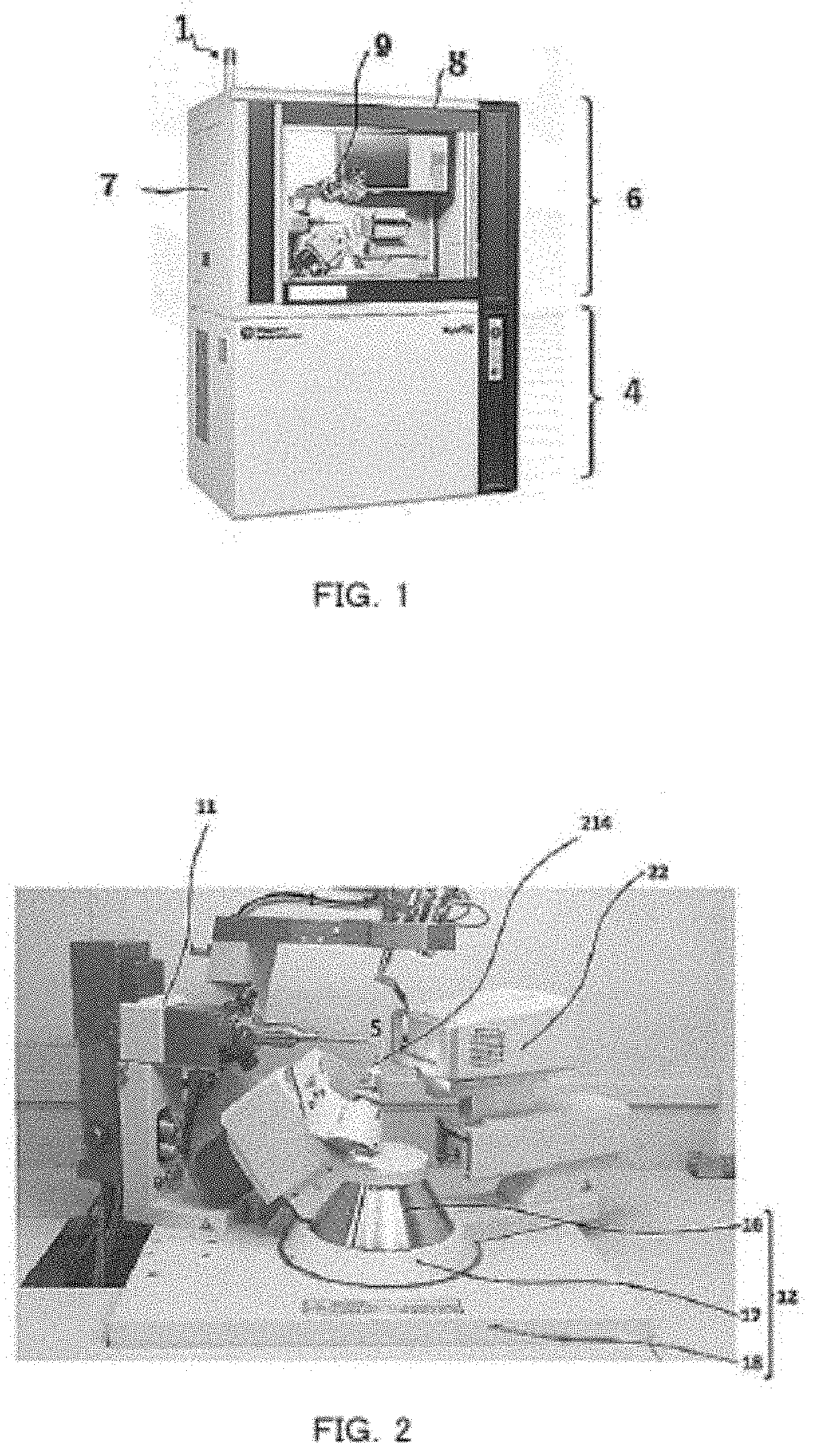
[0066]FIG. 8 shows a sectional view of the sample holder 214 according to Example 1. The sample holder 214 comprises a disk-shaped base part 201 made of metal or the like, attached to the goniometer head (Refer to FIG. 7A) at the tip of the goniometer 12, and a protrusion part 202 formed in a protrusion shape extending downward from one surface thereof (the lower surface in the figure). The protrusion part 202 comprises s conical part 202a, and a sample holding part (corresponding to the so-called goniometer head pin) 202b formed in a protrusion shape. The crystalline sponge 200 in which the above-described sample to be analyzed is soaked is combinedly attached to the sample holder 214 beforehand at a predetermined position of the tip of the sample holding part 202b.
[0067]Further, an attachment part 203 in a recessed truncated cone shape is formed on the other surface (upper surface in the figure) of the base part 201, and a magnet that is not shown in the figure or a projected engagement part (or recessed part) 203a is provided on a contact surface with the goniometer head 15 at the tip of the foregoing goniometer 12 in this attachment part 203. By having this mechanism, the sample holder 214 can be attached/detached to/from the goniometer head 15 at the tip of the goniometer 12, and can be easily and accurately attached thereto by anyone.
[0068]The outer diameter on the base part side of the conical part 202a of the sample holder 214 is set to be smaller than the outer diameter of the base part 201, and an annular-shaped step part 208 is formed. Further, through-holes 204 and 205 passing from the base part 201 to the protrusion part 202 are formed as a sample introduction structure, and seal parts 206 and 207 each for airtightly sealing a hole interior are provided in respective through-holes 204 and 205.
[0069]FIG. 9 shows a perspective view of an applicator 300 as a tool for storing the sample holder 214, and soaking a sample in a crystalline sponge 200, that is attached beforehand to the sample holder 214. FIG. 10 is a sectional diagram of a sample holder unit 400 comprising an applicator 300, and a sample holder 214 stored inside it.
[0070]The applicator 300, in whose inside a storing space 301 for storing the sample holder 214 is formed, and further at whose upper portion the sample holder 214 is fitted in and an opening 302 for taking it out is formed, is formed of a transparent or opaque member such as for example, glass, a resin, metal or the like. On an annular bottom surface of the opening 302, provided is, for example, an annular seal part (O-ring) 304, and during storing of the sample holder 214, the step part 208 of the sample holder 214 is airtightly maintained between the sample holder 214 and the applicator 300 by coming into contact with the seal part 304.
[0071]The inner diameter of the opening 302 of the applicator 300 is set to be slightly larger than the outer diameter of the base part 201 of the sample holder 214, and thus the inner wall of the opening 302 can be made to be a guide surface when inserting/ejecting the sample holder 214 thereinto/therefrom. Thus, preparation can be easily made without giving any damage to the sample S when removing the sample holder 214 comprising the crystalline sponge 200 in which a very small amount of a sample is soaked, from the applicator 300.
[0072]Symbols 315 and 315 representing a pair of put-out prevention parts (L-shaped swing levers) provided on side surfaces (side walls) of the applicator 300 swing in such a manner that their tips (lateral bars as described later) are moved to positions protruding and retracted to/from the inside of the opening 302. The put-out prevention parts 315 and 315 each are formed from a lateral bar 317 and a vertically upright bar that are formed into an L-shape, and the vertically upright bar comprises an upper portion 319 and a lower portion (operation part) 318 that are formed into a dog-legged shape. The upper portion 319 is connected to the lateral bar 317, and a boundary between the lower portion 318 and the upper portion 319 is supported by a lateral shaft 316 fixed on a side surface of the applicator 300 in a swingable manner. The put-out prevention parts 315 and 315 are energized in each direction (closing direction) where the tip of the lateral bar 317 protrudes toward the opening 302, with a spring that is not shown in the figure. Normally, the lateral bar 317 protrudes toward the opening 302 and the operation part 318 of the vertically upright bar is separated from the side surface of the applicator 300 by this energization. The lateral bar 317 is moved to a retracted position (open state) by pressing the operation part 318 in the side surface direction of the applicator 300 with hand fingers or a manipulator.
[0073]When storing the sample holder 214 in the applicator 300, the operation part 318 of the pull-out prevention part 315 is pressed in a horizontal arrow direction as shown in FIG. 10 with hand fingers or the like to insert the sample holder in the opening 302 in a state where the lateral bar 317 of the pull-out prevention part 315 is opened. Next, when releasing the pressing force in the horizontal arrow direction, that is applied to the operation part 318 of the pull-out prevention part 315 while pushing down the sample holder 214, the pull-out prevention part 315 is rotated by force energized by a spring, and the lateral bar 317 protrudes toward the opening 302.
[0074]When showing the above-described state in FIG. 11, the lateral bar 317 of the pull-out prevention part 315 is engaged with the upper surface of the sample holder 214, and thus the sample holder is prevented from being pulled out from the opening 302 of the applicator 300. In addition, each position of engaging the lateral bar 317 with the upper surface of the sample holder 214 is a position avoiding through-holes 204 and 205.
[0075]FIG. 12 shows a step of introducing a sample into the applicator 300. Sample introduction pipes (hereinafter, also referred to simply as pipes) 220 and 221 each as a sample introduction structure are inserted into the respective through-holes 204 and 205 of the sample holder 214. In FIG. 12, symbol 230 represents a hydrophobic solvent (for example, cyclohexane) injected at the bottom part of the applicator 300, and setting is made to a level at which the crystalline sponge 200 at the tip part of the sample holding part 202b is immersed to fill it therewith. The pipe 220 is a sample injection pipe, and the pipe 221 is a discharge pipe. The tip of the pipe 220 extending to the vicinity of the crystalline sponge 200 is dipped in the solvent 230, and the tip of the pipe 221 extends to a position of not being immersed in the solvent 230. In FIG. 12, when a sample (for example, gas) is injected from the injection pipe 220, the sample is penetrated in the solvent 230, and soaked into the crystalline sponge 200 inside the solvent. The sample (comprising a solvent or a carrier) excessively supplied thereto is discharged outside via the pipe 221.
[0076]Thereafter, in the present example, the pipes 220 and 221 are simultaneously pulled out, and the sample holder 214 comprising the crystalline sponge 200 in which the sample is soaked is subsequently attached to the goniometer head 15 at the tip of the goniometer 12. In addition, the sample holder 214 and the applicator 300 as a tool to be handled therefor are used together in combination as a sample holder unit 400, and are prepared by the number required for an analysis operation and stored in a box-shaped container, that is, are also possible to be provided as a set.
[0077]According to the sample holder unit 400 with the above-described configuration, the crystalline sponge 200 attached to the tip of the pin-shaped holding part 202b (corresponding to a goniometer head pin) constituting part of the sample holder 214 can be safely and easily handled without damage, or deviation from the sample holder 214. That is, the crystalline sponge 200 in which a very small amount of the sample is soaked can be safely, simply and easily prepared on the goniometer head 15 in a short and quick period of time in such an extent that no damage occurs due to drying, without any damage due to taking only it out from a soaking container unlike a conventional manner. According to the present Example, the sample holder 214 with which soaking of the sample is completed is removed from the applicator 300, and is attached to the goniometer head 15 (Refer to FIG.7A) at the tip portion of the goniometer 12. In this manner, the sample S soaked in the crystalline sponge 200 is easily, precisely and quickly arranged at a predetermined position inside the single-crystal X-ray diffractometer 9 without requiring highly specialized knowledge and precise operations.
[0078]Next, described is soaking a sample in the crystalline sponge 200 inside the sample holder unit 400 (Refer to FIGS. 10 to 12) with the above-described configuration, that is performed using a soaking machine.
[0079]In FIG. 13, a very small amount of the sample S extracted by LC (liquid chromatography) 601, GC (gas chromatography) 602, and further, SFC (supercritical fluid chromatography) 603, CE (capillary electrophoresis) 604 and so forth that constitute a pretreatment device 600 is supplied to a pair of the sample introduction pipes 220 and 221 inserted in the through-holes 204 and 205 of the sample holder 214 via the soaking apparatus (soaking machine) 650 provided with every kind of a switching valve and a pressure adjustment device, that supplies a fluid under the necessary conditions (flow rate and pressure), and the sample is selectively introduced into the storing space 301 inside the applicator 300. That is, the sample is sent to the sample introduction pipe 220 on the supply side from the supply side pipe, and is supplied to the sample holder 214 inside the applicator 300 from the tip portion of the sample introduction pipe 220 on the supply side. Only the sample, or a solution in which the sample and the preserving solvent are mixed is supplied by flowing inside the sample introduction pipe 220 on the supply side. In this manner, a very small amount of the sample S introduced thereinto comes into contact with the crystalline sponge 200 attached to the tip of the pin-shaped holding part 202b of the sample holder 214 inside the storing space 301 of the applicator 300, and the sample is soaked therein. In addition, examples of the electrophoresis device herein include various electrophoresis devices concerning capillary electrophoresis, isoelectric point electrophoresis, and so forth. When using a soaking machine, in a state where the sample is injected thereinto, the excessive sample or a solution in which the sample and the preserving solvent are mixed is discharged from the sample introduction pipe 221 on the discharge side, after a predetermined time has elapsed. When not using the soaking machine, the unnecessary preserving solvent or solution flows inside a sample introduction pipe 221 on the discharge side, and is discharged. Accordingly, it is possible that no sample flows through the sample instruction pipe 221 on the discharge side. In addition, when a gas and a supercritical fluid each are set as a carrier, the carrier containing a sample is discharged.
[0080]Next, attaching a sample holder unit into a single-crystal X-ray structure analysis apparatus is described, the sample holder unit comprising a crystalline sponge in which the sample according to the Example 1 is soaked.
[0081]After soaking the sample in the crystalline sponge 200 as shown in FIG. 12, the pipes 220 and 221 are pulled out, and the sample holder unit 400 formed from the sample holder 214 comprising the crystalline sponge 200 in which the sample is soaked, and the applicator 300 for storing the sample holder is attached to the goniometer head 15 at the tip of the goniometer 12 in the single-crystal X-ray diffractometer 9 in the upside-down attitude (in the state where the crystalline sponge 200 is directed upward) by being held with hand fingers, a manipulator 410 or the like, as shown in FIG. 14. At this time, a portion of the attachment part 203 of the sample holder 214 is attached to the goniometer head 15.
[0082]Next, as shown in FIG. 15, the operation parts 318 of the pull-out prevention parts 315 on both sides are pressed in the horizontal arrow directions by hand fingers or the like to open the lateral bars 317. The pull-out prevention of the sample holder 214 is released by disengaging the pull-out prevention parts 315 from the sample holder 214. The applicator 300 is separated from the sample holder 214 by elasticity of the seal part 304, and thus rises in the vertical arrow direction. Then, only the sample holder 214 is to be a state of being attached to the goniometer head 15 at the tip of the goniometer 12 by holding and raising the applicator 300 with hand fingers, a manipulator 410 or the like. At this time, the sample holder 214 is easily and precisely attached to the goniometer head 15 at the tip thereof by a magnet or the like at the attachment part 203.
[0083]In addition, as described above, when the pull-out prevention parts are released, it is so constituted that the applicator 300 is separated from the sample holder 214 by the elasticity of the seal part 304, and thus the seal part 304 serves as separation means of separating (pulling apart) the applicator 300 from the sample holder 214, together with a sealing function. The other means such as a spring or the like energized so as to separate between the applicator 300 and the sample holder 214, other than the seal part 304 may be provided for this separation means. This separation means is similarly applied to Example 2 and Example 3 as well as described later.

Example

EXAMPLE 2
[0084]FIG. 16 is a perspective view showing the applicator 500 of Example 2, according to the present invention; FIG. 17 shows a cross-section of a sample holder unit according to the same; and the same symbols are given the same portions as those in Example 1. Symbol 501 represents a plate-shaped pull-out prevention part (sliding part) that protrudes toward the opening 302 by sliding in the lateral direction along an opening surface 509 of the applicator 500. The pull-out prevention part 501 is engaged with the upper surface of the sample holder 214 stored in the applicator 500 in an attached state thereof, and prevents the sample holder 214 from being pulled out from the opening 302. Symbols 504 and 504 represent guide rails each whose cross-section is U-shaped, the guide rails are arranged so as to extend in parallel at both side portions of the opening surface 509. The pull-out prevention part 501 whose both side ends (engagement parts) are engaged with the guide rails 504 and 504 is slidably guided in both directions of each arrow.
[0085]The pull-out prevention part 501 having a U-shaped opening part 502 in the central part is provided with an operation part 505 on the U-shaped circular arc side of the opening part 502 that is opened on the other side 506. Attaching the pull-out prevention part 501 to the applicator 500 is performed by pressing the operation part 505 with hand fingers or a manipulator while pushing down the upper surface of the sample holder 214, and sliding the pull-out prevention part 501 (Refer to FIG. 17).
[0086]The pull-out prevention part 501 whose opening part 502 has an inner diameter smaller than an outer diameter of the base part 201 of the sample holder 214 is engaged with only the outer peripheral portions of the upper surface of the sample holder 214 so as not to cover the through-holes 204 and 205, when it is attached into the applicator 500. The pull-out prevention part 501, at a front end of which an inclined surface 503 is provided to a sliding lower surface, is made to be attached thereto while pushing down the upper surface of the sample holder 214 by the inclined surface 503 via sliding and engaging therewith, and sliding between the upper surface of the sample holder 214 and the opening surface 509 of the applicator 500 is smoothly performed.
[0087]When soaking the sample in the crystalline sponge 200, the sample introduction pipes 220 and 221 are inserted into the through-holes 204 and 205 of the sample holder 214, that are exposed to the opening part 502 of the pull-out prevention part 501 in the state where the pull-out prevention part 501 is attached thereto to introduce the sample similarly to Example 1.
[0088]FIG. 18 shows a sectional view at the time when a sample holder unit according to Example 2 is attached to a goniometer in a single-crystal X-ray structure analysis apparatus. The sample holder unit 400 as shown in FIG. 17 is attached to the goniometer head 15 at the tip of the goniometer 12 in the upside-down attitude with hand fingers, a manipulator 410 or the like as shown in FIG. 18. At this time, the attachment part 203 portion of the sample holder 214 is attached to the goniometer head 15 at the tip of the goniometer 12.
[0089]Next, the pull-out prevention part 501 is pulled out in the direction (right direction in FIG. 16) opposite to that at the time of its attachment thereto by operating the operation part 505 with hand fingers, a manipulator 410 or the like. When the pull-out prevention part 501 is pulled out from the applicator 500, the applicator 500 is separated from the sample holder 214 by elasticity of the seal part 304 by releasing the pull-out prevention of the sample holder 214, and thus rises in the vertical arrow direction. Then, only the sample holder 214 remains attached to the goniometer head 15 at the tip of the goniometer 12 by holding and raising the applicator 300 with hand fingers, a manipulator 410 or the like. Similarly to Example 1, the sample holder 214 is easily and precisely attached to the goniometer head 15 at the tip of the goniometer 12 by a magnet or the like at the attachment part 203. The sample holder 214 is freely attached to the tip portion of the goniometer 12 in an attachable/detachable manner by this positioning mechanism.
[0090]According to Example 2, the pull-out prevention can be easily and surely performed since a pull-out prevention part is attached thereto by sliding; and the sample holder 214 can be quickly, easily and precisely attached to the goniometer 12 while protecting the crystalline sponge 200, since the sample holder 214 together with the applicator 500 is carried and attached to the goniometer 12, and only the applicator 500 is subsequently separated therefrom.

Example

EXAMPLE 3
[0091]FIG. 19 is a perspective view in which a sample holder unit 400 is shown with a partial cross-section according to Example 3 of the present invention, and the same symbols are given the same portions as those in Example 2. FIG. 19 shows a state of attachment thereof into an applicator by the pull-out prevention part 701, and it is omitted to show a U-shaped opening part (Refer to symbol 502 in FIG. 16) of a pull-out prevention part according to Example 2.
[0092]Symbol 700 represents an applicator, and symbol 701 represents a pull-out prevention part (sliding part) for sliding an opening (that is not shown in the figure) of the applicator 700, that is formed of a resin or the like in plate thickness exhibiting high mechanical strength (about 10 atmospheric pressure). Symbols 704 and 704 representing a pair of guide rails arranged in parallel so as to extend in the lateral direction at both side portions above the applicator 700 exhibit high mechanical strength, the guide rails each whose face is U-shaped, are formed in plate thickness exhibiting strength (about atmospheric pressure). Symbols 705 and 705 representing engagement parts at both side ends 703 of the pull-out prevention part 701, the engagement parts each whose cross-section is channel-shaped (U-shaped), are formed of a resin or the like exhibiting high mechanical strength so as to be engaged with the guide rails 704 and 704. Symbol 707 representing a protrusion-shaped operation part provided on a top plate 702 of the pull-out prevention part 701 is used for a sliding operation of the pull-out prevention part 701. Further, it is omitted to show the figure, but similarly to Example 2, an inclined surface is provided to a sliding lower surface at a front end of the pull-out prevention part 701, and smooth sliding between the sample holder 214 and the applicator 700 is made possible.
[0093]The attachment thereof into the applicator 700 is performed by engaging the engagement parts 705 and 705 of the pull-out prevention part 701 with the guide rails 704 and 704, and slidably operating the operation part 707 in the arrow direction with hand fingers, a manipulator or the like. The pull-out prevention part 701 is engaged with the upper surface of the sample holder 214 in the attached state thereof, and suppresses the pull-out thereof from the applicator 700. The removal of the pull-out prevention part 701 therefrom is carried out by operating the operation part 707 in the direction opposite to that at the time of attachment thereof to remove the pull-out prevention part 701 from the guide rails 704 and 704.
[0094]During attachment thereof into a single-crystal X-ray structure analysis apparatus, the sample holder unit 400 shown in FIG. 19 is held by hand fingers, a manipulator or the like, and is attached to the goniometer head 15 at the tip of the goniometer 12 in the upside-down attitude. At this time, the attachment part 203 of the sample holder 214 is attached to the goniometer head 15 at the tip of the goniometer 12. Next, in the state of pressing the applicator 700, the pull-out in the direction (right direction in FIG. 16) opposite to that at the time of attachment thereto is performed by operating the operation part 707 with hand fingers, a manipulator 410 or the like. The applicator 700 is separated from the sample holder 214, and raised with elasticity of the seal part 304 by pulling out the pull-out prevention part 701. Then, when the applicator 700 is held and raised by hand fingers, a manipulator or the like, only the sample holder 214 remains attached to the goniometer head 15 at the tip of the goniometer 12.
[0095]According to Example 3, similarly to Example 1 and Example 2, the sample holder 214 together with the applicator 700 is carried and attached to the goniometer 12, and only the applicator 700 is subsequently separated therefrom, and thus the sample holder 214 can be quickly, easily and precisely attached to the goniometer 12 while protecting the very small and fragile crystalline sponge 200.
[0096]As described above in detail, according to a sample holder unit for a single-crystal X-ray structure analysis apparatus of the present invention, the single-crystal X-ray structure analysis using a very small and fragile crystalline sponge can be quickly, surely and easily performed without accompanying the conventionally required fine and precise operation, even if not having specialized knowledge of X-ray structure analysis, in other words, there is provided the sample holder unit capable of realizing a very versatile and user-friendly single-crystal X-ray structure analysis apparatus that is capable of high-yield and efficient performance of the single-crystal structure analysis using the crystalline sponge. Further provided is a sample holder unit having a configuration more adaptable to the actual sample preparation operation.
[0097]In the step of soaking a sample into the crystalline sponge 200, the sample is supplied to the sample holder unit 400 set to a temperature, a pressure and so forth that are suitable for soaking from the soaking apparatus (soaking machine) 650 (Refer to FIG. 13) under the suitable conditions for soaking (a pressure, a flow rate and so forth). Thus, the inside of the sample holder unit 400 needs to correspondingly deal with various temperatures and pressures. In the present Example 3, the pull-out prevention part 701, the engagement part 705 and the guide rails 704 in plate thickness exhibiting high mechanical strength (about 10 atmospheric pressure) are used, and further, the engagement part 705 and the guide rails 704 each are formed into its channel-shaped (U-shaped) cross-section type exhibiting high mechanical strength (about 10 atmospheric pressure), thereby being responsively and sufficiently endurable in the foregoing.
[0098]In addition, though various examples according to the present invention are described above, the present invention is not limited to the above-described Examples and includes various modified examples. For example, the above-described Examples describe the entire system in detail in order to facilitate understanding of the present invention, but are not necessarily limited to those having all the configurations that have been described. Further, a part of a configuration of one Example may be replaced with a configuration of another Example; further, a configuration of another Example may also be added to a configuration of one Example; and with respect to a part of a configuration of each Example, further performed may be addition/deletion/replacement of another configuration.
[0099]The present invention is widely applicable for an X-ray structure analysis apparatus used for searching a material structure, a method thereof, and so forth.
[0100]In addition, the present international application claims priority under Japanese Patent Application No. 2018-219782, filed Nov. 22, 2018, and the entire content of Japanese Patent Application No. 2018-219782 is applied to the present international application.
EXPLANATION OF THE SYMBOLS
[0101]1. . . Single-crystal X-ray structure analysis apparatus (whole); 9. . . Single-crystal X-ray diffractometer; 11. . . X-ray tube; 12. . . Goniometer; 15. . . Goniometer head; 22. . . X-ray detector; 102. . . Measurement device; 103. . . Input device; 104. . . Image display device; 107. . . CPU; 108. . . RAM; 109. . . ROM; 111. . . Hard disk; 116. . . Analysis application software; 117. . . Measurement application software; 200. . . crystalline sponge; 201. . . Base part; 202. . . Protrusion part; 204, 205. . . Through-hole; 214. . . Sample holder; 300, 500, 700. . . Applicator; 301. . . Storing space; 302. . . Opening; 220, 221. . . Sample introduction pipe (Pipe); 315, 501, 701. . . Pull-out prevention part; 318, 505, 707. . . Operation part; and 400. . . Sample holder unit.

PUM

no PUM

Description & Claims & Application Information

We can also present the details of the Description, Claims and Application information to help users get a comprehensive understanding of the technical details of the patent, such as background art, summary of invention, brief description of drawings, description of embodiments, and other original content. On the other hand, users can also determine the specific scope of protection of the technology through the list of claims; as well as understand the changes in the life cycle of the technology with the presentation of the patent timeline. Login to view more.

Similar technology patents

Microfluidic device with pwm controlled PCR heater

InactiveUS20110312700A1Easily usableFaster and precise temperature cyclingBioreactor/fermenter combinationsValve arrangementsCMOSPolymerase chain reaction
Owner:GENEASYS

Module and device for emitting electromagnetic waves

PendingUS20200253822A1Easily usableEffectively treat painElectrotherapyDiagnosticsPhysicsEngineering
Owner:REMEDEE LABS

Classification and recommendation of technical efficacy words

  • Easily usable
  • Easily carry-out

High Density Optical Packaging Header Apparatus

InactiveUS20120257857A1Highly flexibleEasily usableCoupling light guidesMulti-mode optical fiberBackplane
Owner:CHIRAL PHOTONICS

Package closure and labeling construction

InactiveUS6845577B1Easily usableEffectively constructStampsBagsEngineering
Owner:TIPPER TIE

Lockable attachment and styptic device including same

InactiveUS20130131721A1Easily manufacturableEasily usableSlide fastenersFlexible elementsBiomedical engineeringTongue blades
Owner:BENRIKAL SERVICES

Microfluidic device with pwm controlled PCR heater

InactiveUS20110312700A1Easily usableFaster and precise temperature cyclingBioreactor/fermenter combinationsValve arrangementsCMOSPolymerase chain reaction
Owner:GENEASYS
Why Eureka
Try Eureka