Load-detecting orthosis

Pending Publication Date: 2022-01-06
GOLEX AG
View PDF0 Cites 0 Cited by
  • Summary
  • Abstract
  • Description
  • Claims
  • Application Information

AI Technical Summary

Benefits of technology

[0013]It is desirable to specify a loading-detecting orthosis of inexpensive design that is still able to output precise warnings. It is also desirable to avoid false alarms. Furthe

Problems solved by technology

Specifically, excessive pressure loading events often occur when a user for ex

Method used


Image

  • Load-detecting orthosis
  • Load-detecting orthosis

Examples


Example

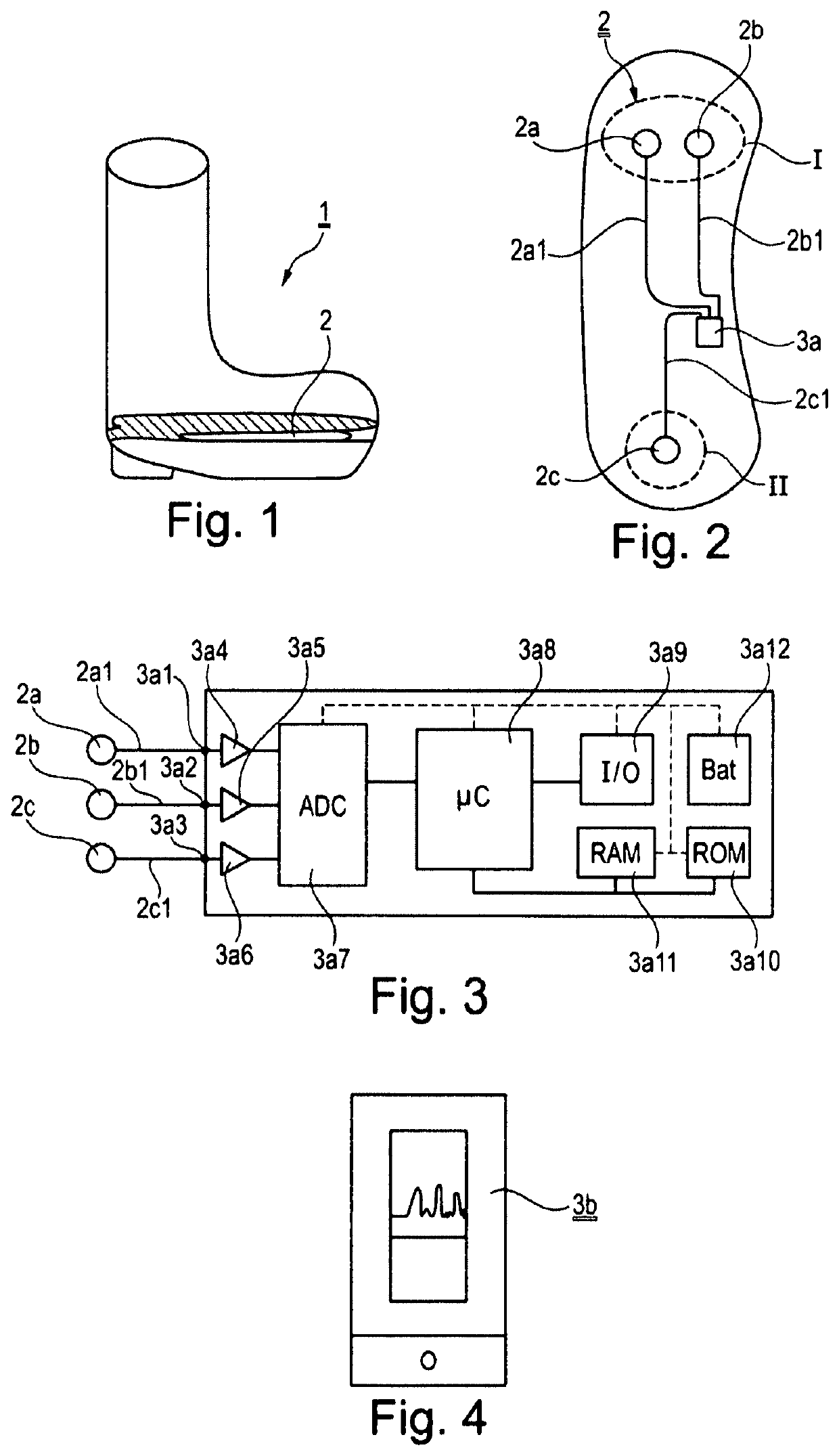
[0046]According to FIG. 1, a loading-detecting orthosis 1, referenced generally by 1, comprises a sensor 2 that generates sensor signals and that has sensor elements 2a, 2b, 2c (cf. FIG. 2) in pressure areas, indicated by dashed circles I and II, and sensor signal-evaluating electronics 3 therefor that are designed to indicate loading critical to the orthosis user, wherein the sensor signal-evaluating electronics 3a, 3b (cf. FIG. 4) are designed to ascertain characteristic values regarding pressure loading events detected per pressure area by way of the sensor elements 2a, 2b, 2c, to form a sum value into which the characteristic values are incorporated by amount in weighted form such that at least 3 different weightings are used, and to generate an alert signal when the sum value exceeds a certain amount.

[0047]The loading-detecting orthosis 1 in the illustrated exemplary embodiment is in this case an orthosis able to be used for example following a tibia fracture, in which the bone...


PUM


Abstract

A loading-detecting orthosis includes a sensor that generates sensor signals and that has sensor elements in pressure areas. The loading-detecting orthosis further includes sensor signal-evaluating electronics that are designed to indicate critical loading. The sensor signal-evaluating electronics are designed to ascertain characteristic values regarding pressure loading events detected at least per pressure area by way of the sensor elements, to form a sum value into which the characteristic values are incorporated by amount in weighted form such that at least three different weights are used, and to generate an alert signal when the sum value exceeds a certain amount.

Description

CROSS-REFERENCE TO RELATED APPLICATIONS[0001]The present application is the national stage of International Pat. App. No. PCT / IB2019 / 001419 filed Dec. 3, 2019, and claims priority under 35 U.S.C. § 119 to DE 10 2018 220 853, filed in the Federal Republic of Germany on Dec. 3, 2018, the content of each of which are incorporated herein by reference in their entireties.FIELD OF THE INVENTION[0002]The present invention relates to the detection of a loading.BACKGROUND[0003]Complications often occur following bone fractures and operations in the leg and foot region. For instance, fractures do not heal but rather have to be re-operated on, endoprostheses do not grow in, but rather become loose, etc. Medical practice has shown that, following certain orthopedic interventions, roughly 10% of all patients require new operations merely because the patient has overloaded the critical point.[0004]There are therefore already a large number of proposals as to how to recognize overloading and warn ...

Claims


Application Information

Patent Timeline
IPC IPC(8): A61B5/103A61B5/00
CPCA61B5/1036A61B5/6807A61B2562/0247A61B5/0004A61B5/746A61F5/01A61B5/1038A61F5/0127A61F2005/0155
Inventor WERNER, FRANK
Owner GOLEX AG
Why Eureka
Try Eureka