
Orthodontic wire-bending robot for lingual orthodontic technique

Pending Publication Date: 2022-01-13
GILBERT REISMAN ALFREDO
View PDF0 Cites 6 Cited by
  • Summary
  • Abstract
  • Description
  • Claims
  • Application Information

AI Technical Summary

Benefits of technology

The present invention is a wire bending robot that can perform precise bends on very small wires, up to 180 degrees. It can also bend wires by torque when using wires with profiles other than round. Additionally, the robot has a wireless communication input port, allowing remote control without the need for physical connection. Overall, the invention provides a flexible and efficient tool for wire bending in various situations.

Problems solved by technology

However, even with the above advantages, the correct application of this technique is restricted to the creation of a lingual arch that is as precise as possible, since it requires that the arch be made with a high degree of precision, since it must present a surface that adapts as much as possible to the external shapes of the teeth, adapting even to the imperfections themselves and asymmetries of the patient teeth.
To achieve this, it is commonly used a plaster mold on which the wire is cast to obtain the lingual arch; however, when the mold is used as a support for the forming process, the professional must wait for the complete cure of the mold, which results in significant losses of time.
In addition to the above, since the wire is molded by hand, it does not present the degree of pressure necessary to provide the correct treatment to dental deviations, so in many cases the orthodontic treatment has the risk of not complying with the appropriate quality standards.
Therefore, the described equipment must coordinate its two arms to be able to carry out the bending of the wire, which can seriously limit the number of bends that can be made, since, due to the proximity of the heads, they cannot be obtain arch structures in a “U” shape, far from it with very sharp direction changes.
However, the head used cannot move on the base of the equipment, so it is not possible to include elevations in the wire, the equipment being restricted to making corrections on a single plane of the archwire.
In this equipment, the head is in a fixed work plane, and it is the wire that is turned to obtain bends in three planes X, Y or Z; however, due to the operating plane of the wire holding element, large-format pieces or with 180° bends cannot be manufactured since said pieces would collide with the base of the equipment if it were to make more than one bending on the plane “Z” of the formed piece.
None of the aforementioned equipment allows precise bends in the wire since their bending heads have a very small degree of freedom, in many cases having to rotate the wire on its axis to carry out the necessary bends, having as a consequence a clear limit on the complexity of the formed wire, since it is not possible to make closed bends or carry out lifts with sudden changes in direction, since doing so, the wire would collide with the head causing deformations in the piece created.
Also, due to the type of construction of the heads, most of the bending equipment requires a large work surface, which limits its use in small rooms, and in the case of equipment with articulated arms, the complexity of the equipment increases considerably, which can cause errors due to misalignment of the arms, causing much greater wear on the equipment due to the complexity of the transmission mechanisms required to move the heads. and arms.

Method used


Image

  • Orthodontic wire-bending robot for lingual orthodontic technique
  • Orthodontic wire-bending robot for lingual orthodontic technique
  • Orthodontic wire-bending robot for lingual orthodontic technique

Examples


Embodiment Construction

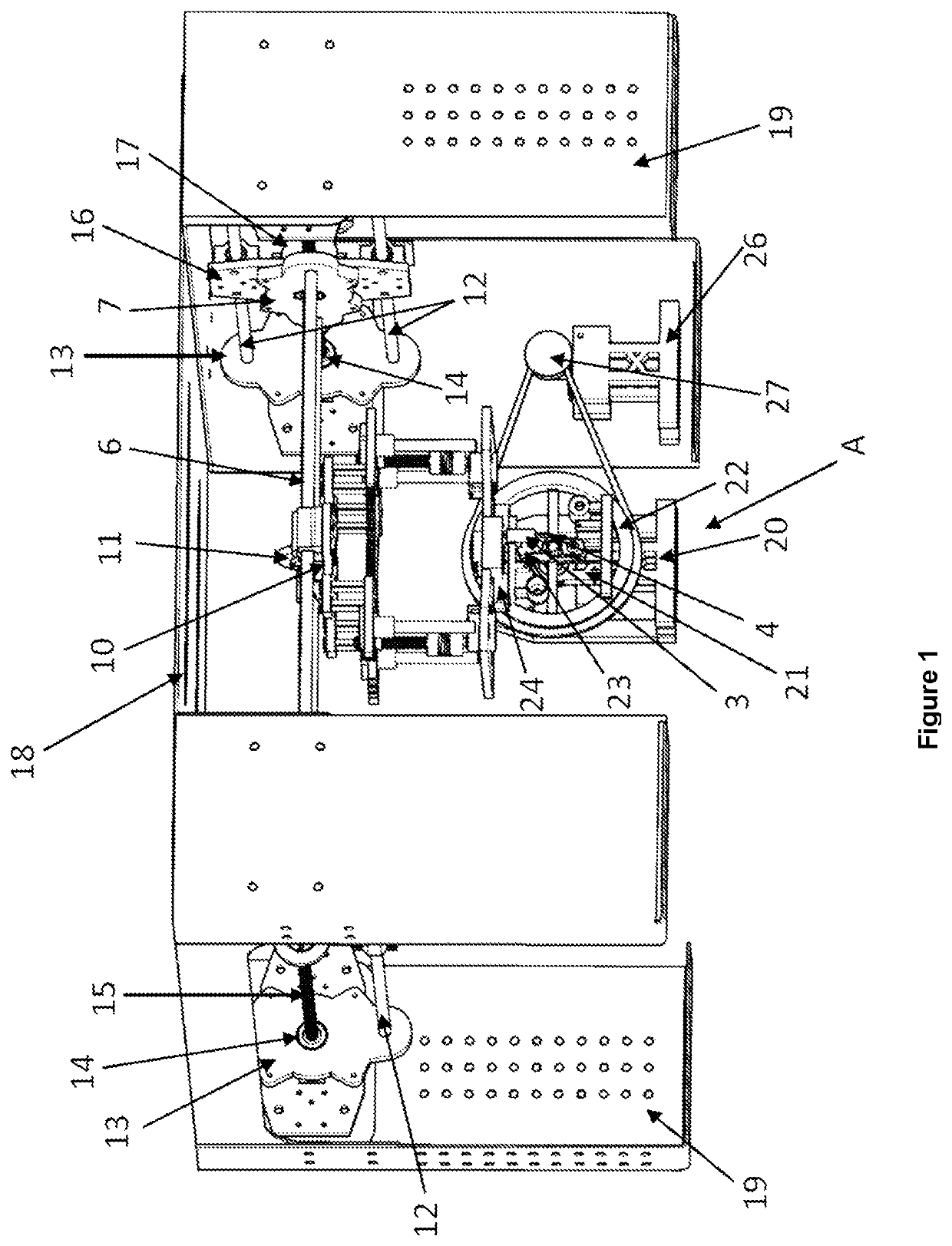
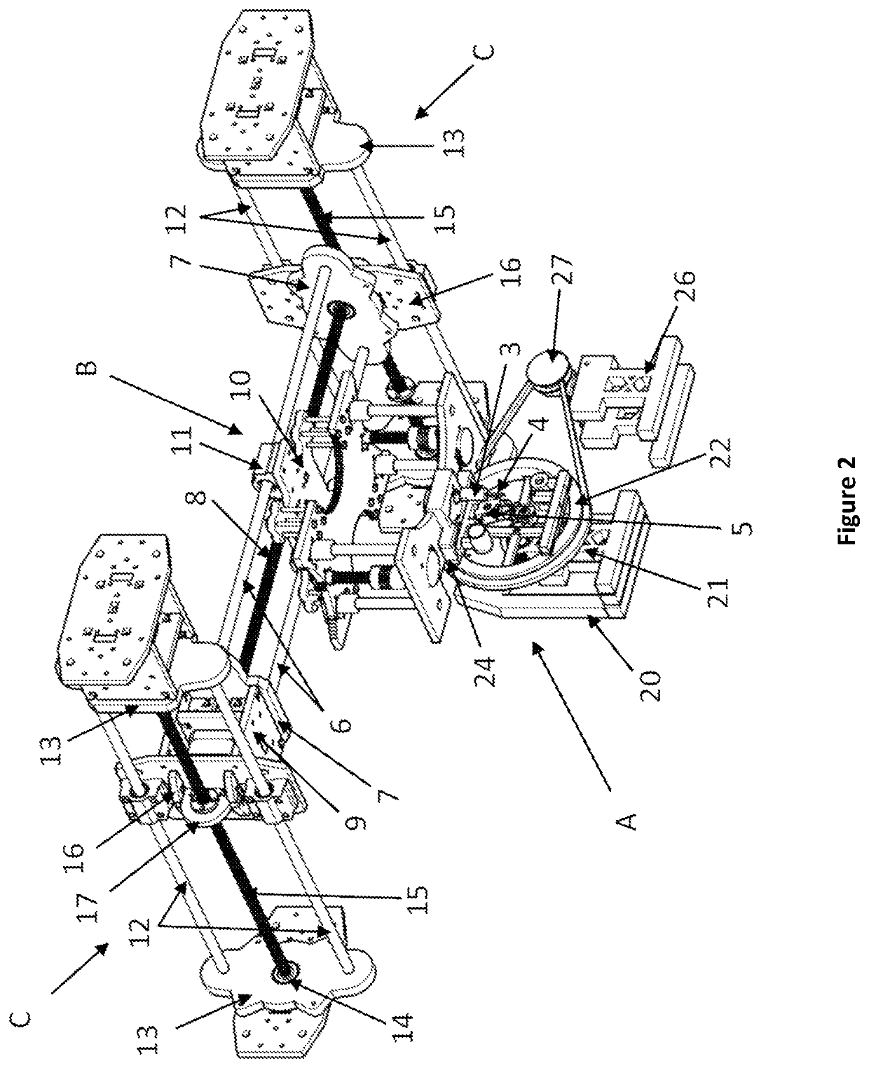
[0020]The present invention provides a novel lingual orthodontic wire bender robot, which allows its bending head to be moved through the X, Y and Z planes along the length, width, and height of the entire length of the central platform of the robot, thereby allowing greater precision in wire bending. The foregoing also provides the robot with the ability to perform bends by torque, carrying out horizontal, vertical, and sagittal compensations, so that the formed orthodontic wire presents inclination in its faces at certain angle and segment to be able to perform front rotation stresses.

[0021]To achieve the above, the lingual orthodontic wire bender robot of the present invention is comprised of:

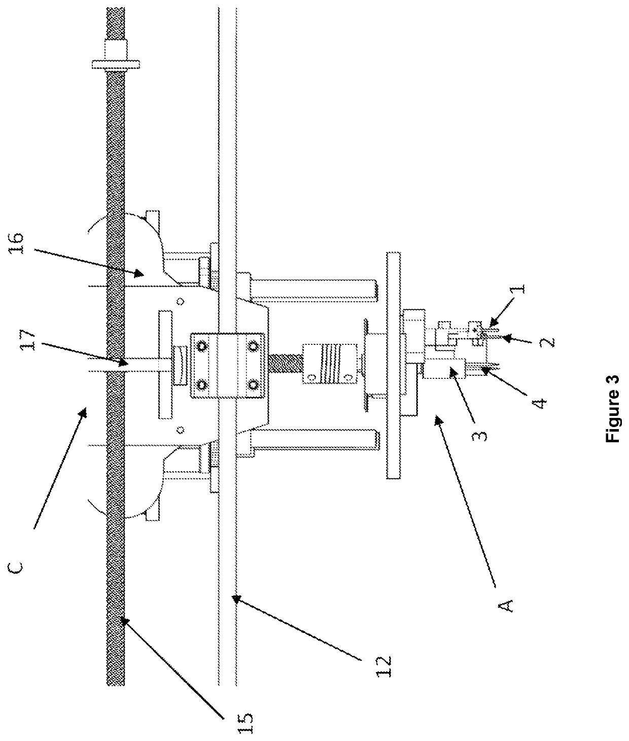
[0022]a bending head (A), with a base having a motor coupled to a vertical lifting spindle that moves the head in the “Z” axis up to 35 mm, the bending head comprising:

[0023]an extrusion mechanism, which controls the advance and retreat of the orthodontic wire, which has a pair of parallel m...


PUM

PropertyMeasurementUnit
Lengthaaaaaaaaaa
Lengthaaaaaaaaaa
Lengthaaaaaaaaaa

Abstract

An orthodontic wire bender robot to be used in the manufacture of orthodontic prostheses, having a cartesian type displacement frame that allows moving the bending head of the equipment along the X, Y and Z-axes, in order to enable the robot to execute bends by torque, performing horizontal, vertical and sagittal compensations so that the shaped orthodontic wire presents an incline on its faces at certain angle and segment in order to execute frontal rotation stresses.

Description

FIELD OF INVENTION[0001]The present invention refers to a novel wire bender robot for the manufacture of wire arches for lingual orthodontics and more particularly, the present invention provides a novel bending robot that allows automating the bending of wires intended to be used within known supports named lingual orthodontic brackets. The present invention allows three-dimensional bending (3D bending); the robot also having means for the displacement of the bending head through the X, Y and Z planes for greater precision and to allow bends by means of torque, performing horizontal, vertical and sagittal compensations to best match the archwire to the contours of the dental pieces where it will be placed, and thus provide the orthodontist with the possibility of elaborating all the bends, compensations and angulations required to carry out an orthodontic treatment.BACKGROUND OF THE INVENTION[0002]Lingual orthodontics is a technique that allows the orthodontic treatment of alignmen...

Claims


Application Information

Patent Timeline
IPC IPC(8): A61C7/20B21F1/00B21F45/00
CPCA61C7/20B21F45/008B21F1/00B21F1/006B21C23/08B25J9/1615B25J11/005B25J13/006
Inventor GILBERT REISMAN, ALFREDO
Owner GILBERT REISMAN ALFREDO
Learn More