
Measuring device

Active Publication Date: 2022-01-13
SIEMENS AG
View PDF5 Cites 0 Cited by
  • Summary
  • Abstract
  • Description
  • Claims
  • Application Information

AI Technical Summary

Benefits of technology

This patent describes a method for reducing the complexity of a computational model used to train a sensor. By learning each movement signal separately, the model can compensate for reduced accuracy caused by shocks. The model uses filters to model the unwanted signals and a difference between the sensor signal and the compensation signal is formed after processing. This simplifies the calculation of the compensation signal and reduces the need for interference mapping. Overall, this invention improves the accuracy and efficiency of sensor training.

Problems solved by technology

However, the mechanical sensitivity of free-hanging metal threads that sag during heating, so that the serviceable life and the measurement accuracy during vibrations are adversely affected.

Method used


Image

  • Measuring device
  • Measuring device

Examples


Embodiment Construction

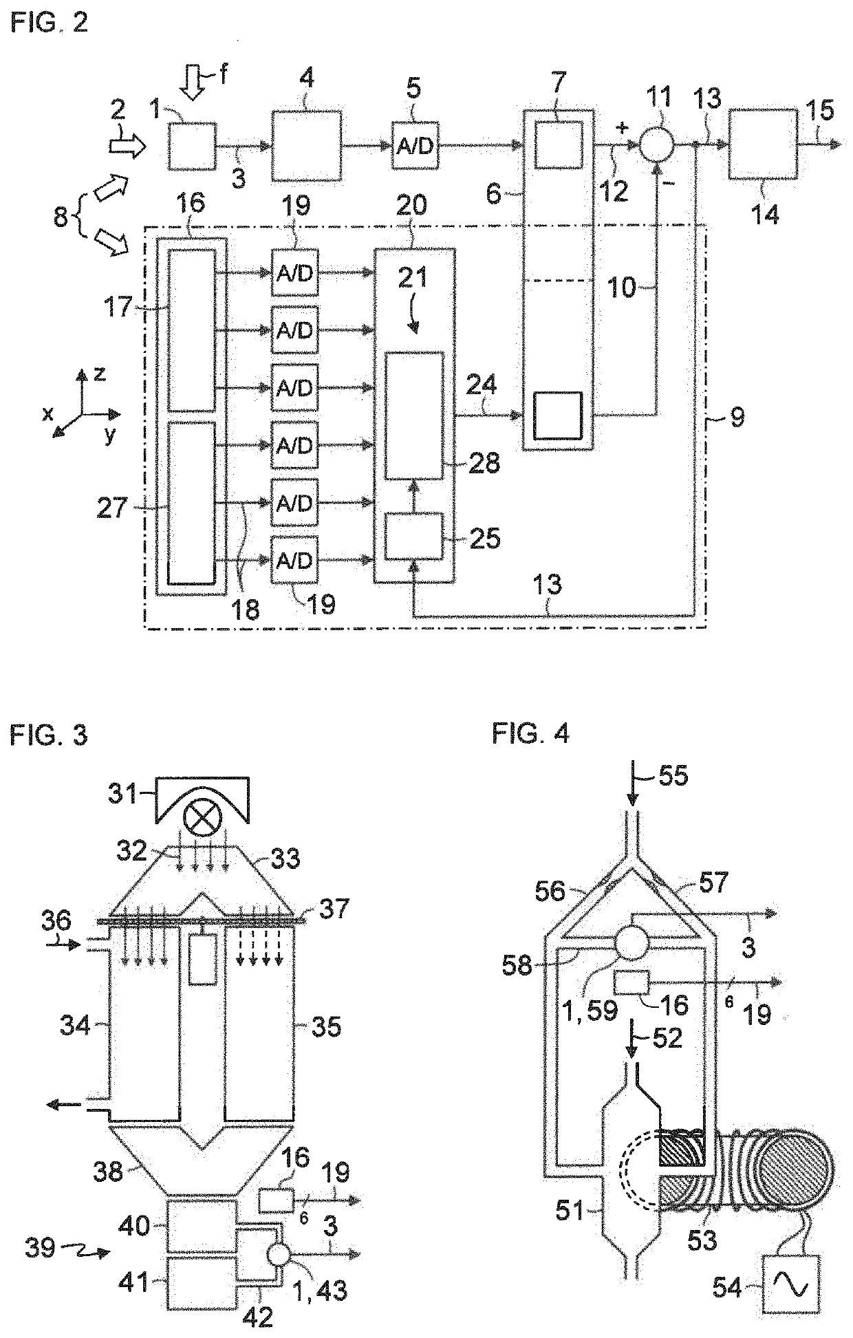
[0020]Throughout all the figures, same or corresponding elements may generally be indicated by same reference numerals. These depicted embodiments are to be understood as illustrative of the invention and not as limiting in any way. It should also be understood that the figures are not necessarily to scale and that the embodiments may be illustrated by graphic symbols, phantom lines, diagrammatic representations and fragmentary views. In certain instances, details which are not necessary for an understanding of the present invention or which render other details difficult to perceive may have been omitted.

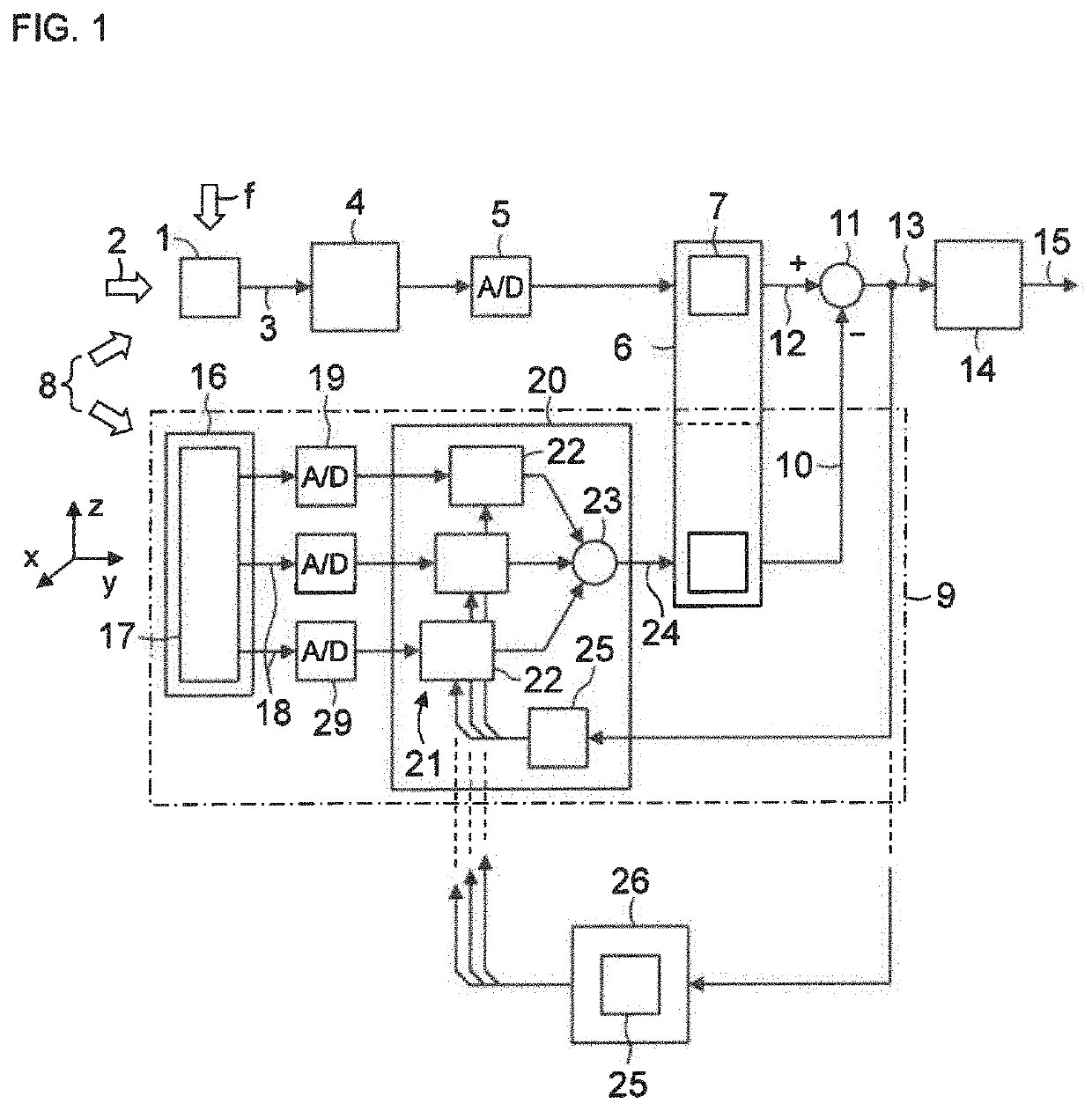
[0021]Turning now to the drawing, and in particular to FIG. 1, there is shown a schematic illustration of one embodiment of a measuring device in accordance with the invention, including a sensor 1 that converts a measured variable 2 into an analog electrical sensor signal (sensor raw signal) 3. The sensor raw signal 3 is filtered and / or amplified in an analog signal preprocessing ...


PUM


Abstract

A measuring device includes a sensor generating a sensor signal in dependence upon a detected measured variable, a compensating facility generating a compensation signal in response to detected shocks, and an evaluating facility generating a measurement result from a difference between the sensor signal and the compensation signal. The compensating facility includes a multi-axis MEMS inertial measuring unit having an acceleration sensor alone or together with a gyroscope and generating a plurality of movement signals in correspondence to a number of axes, and a computer including a computational model trained to model an unwanted signal portion of the sensor signal in response to the shocks caused by the movement signals, and to output the unwanted signal portion as a compensation signal. The computational mod& is trained such that absent a measured variable, the difference between the sensor signal and the compensation signal is zero or is below a predetermined threshold.

Description

CROSS-REFERENCES TO RELATED APPLICATIONS[0001]This application claims the priority of European Patent Application, Serial No. EP 20185402.3, filed Jul. 13, 2020, pursuant to 35 U.S.C. 119(a)-(d), the disclosure(s) of which is / are incorporated herein by reference in its entirety as if fully set forth herein.BACKGROUND OF THE INVENTION[0002]The present invention relates to a shock-sensitive measuring device.[0003]The following discussion of related art is provided to assist the reader in understanding the advantages of the invention, and is not to be construed as an admission that this related art is prior art to this invention.[0004]MEMS acceleration sensors and gyroscopes for detecting movements in drones, mobile telephones, motor vehicles, aircraft and mobile internet of things (IoT) devices are generally known. 3D acceleration sensors measure linear accelerations along three orthogonal axes, however they do not react to angular velocities, 3D gyroscopes measure angular velocities ...

Claims


Application Information

Patent Timeline
IPC IPC(8): G01N27/74G01N33/00
CPCG01N27/74G01N33/0036G01D18/00G01N21/3504G01N21/01G01N2021/0112G01D3/0365G01P21/025G01P15/02G01P15/14G06N3/04G06N3/08
Inventor KIRSAMMER, FLORIANSCHMIDT, BENJAMIN
Owner SIEMENS AG
Learn More