Acoustic wave device

a technology of acoustic waves and resonators, applied in the direction of impedence networks, electrical devices, etc., can solve the problem of difficulty in increasing q to be sufficiently high, and achieve the effect of increasing the impedance ratio of a resonator

Pending Publication Date: 2022-01-13
MURATA MFG CO LTD
View PDF0 Cites 0 Cited by
  • Summary
  • Abstract
  • Description
  • Claims
  • Application Information

AI Technical Summary

Benefits of technology

[0010]In each of acoustic wave devices according to preferred embodiments of the present invention, the impedance ratio of a resonator is able to be increased.

Problems solved by technology

However, it is difficult to increase Q to be sufficiently high in an acoustic wave resonator of the related art that uses a bulk wave.

Method used


Image

  • Acoustic wave device
  • Acoustic wave device
  • Acoustic wave device

Examples


first preferred embodiment

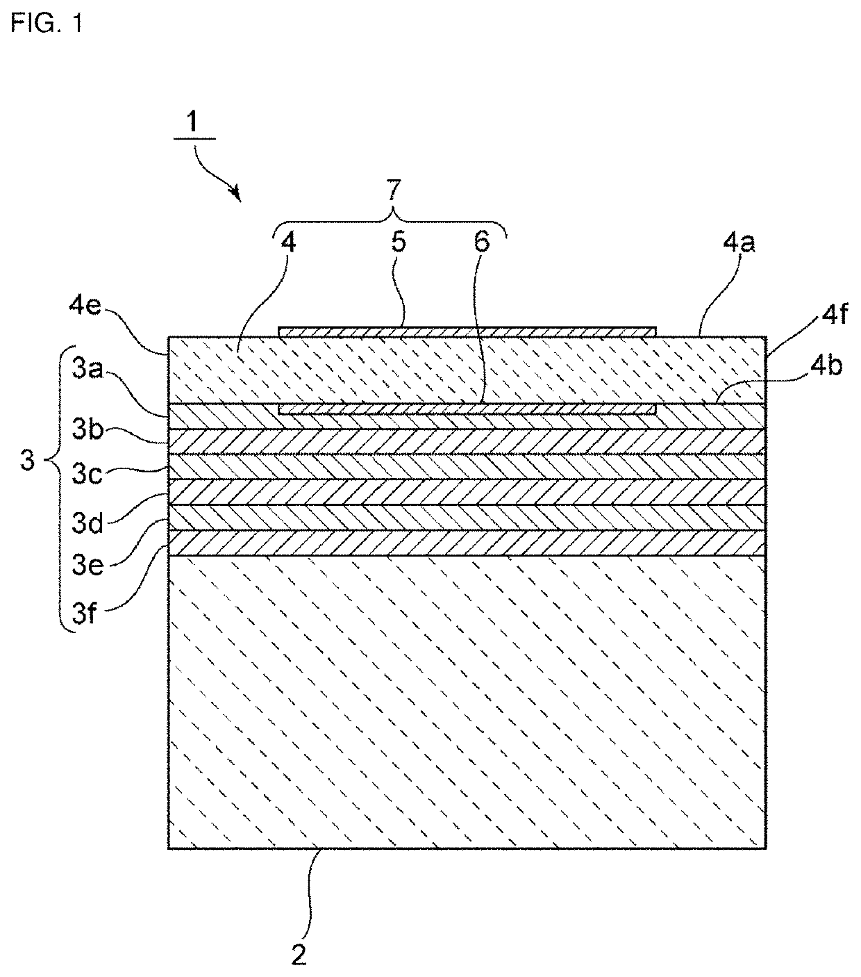
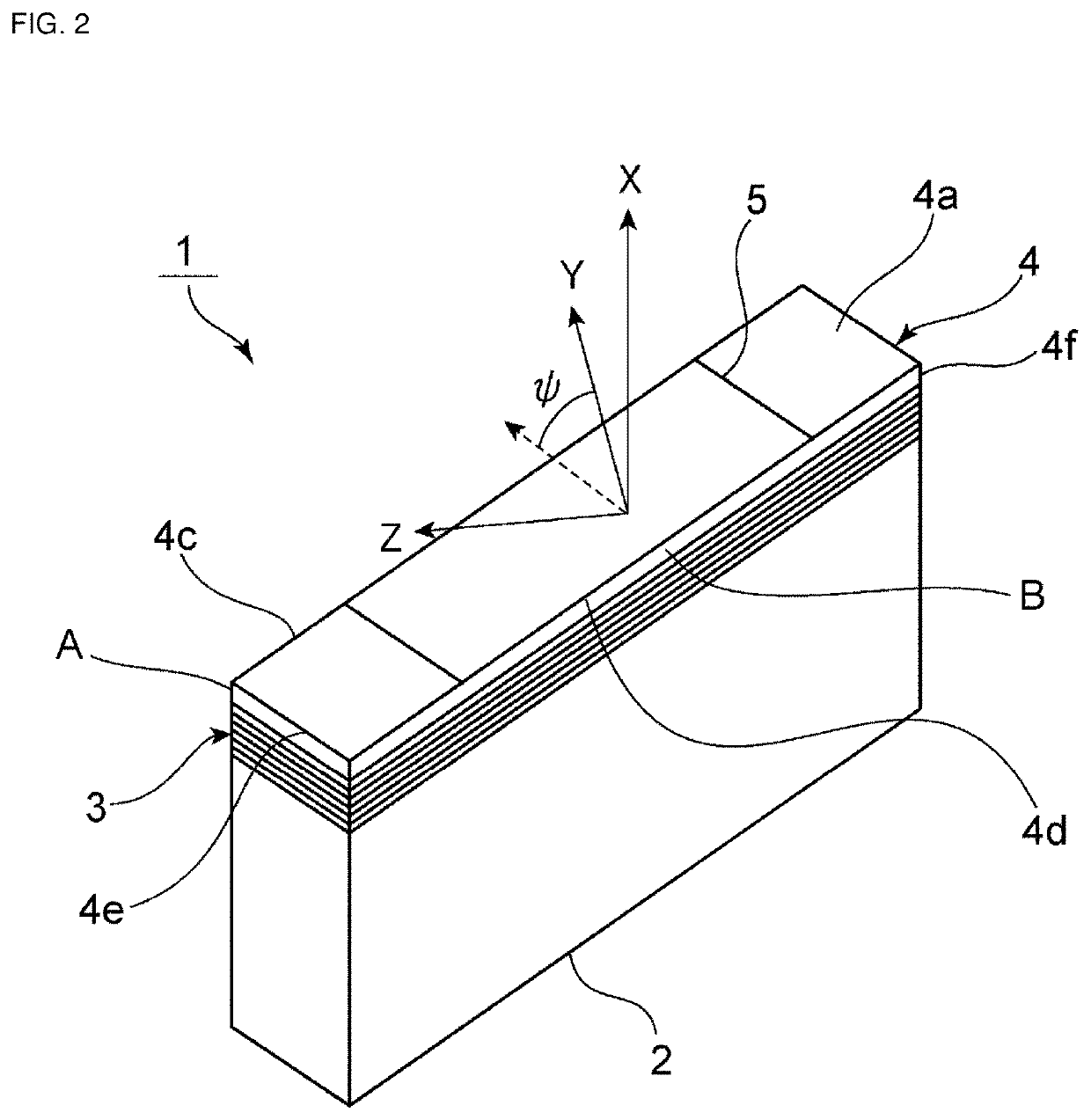
[0041]FIG. 1 is a sectional front view illustrating an acoustic wave device according to the first preferred embodiment of the present invention, and FIG. 2 is a perspective view illustrating the appearance of the acoustic wave device.

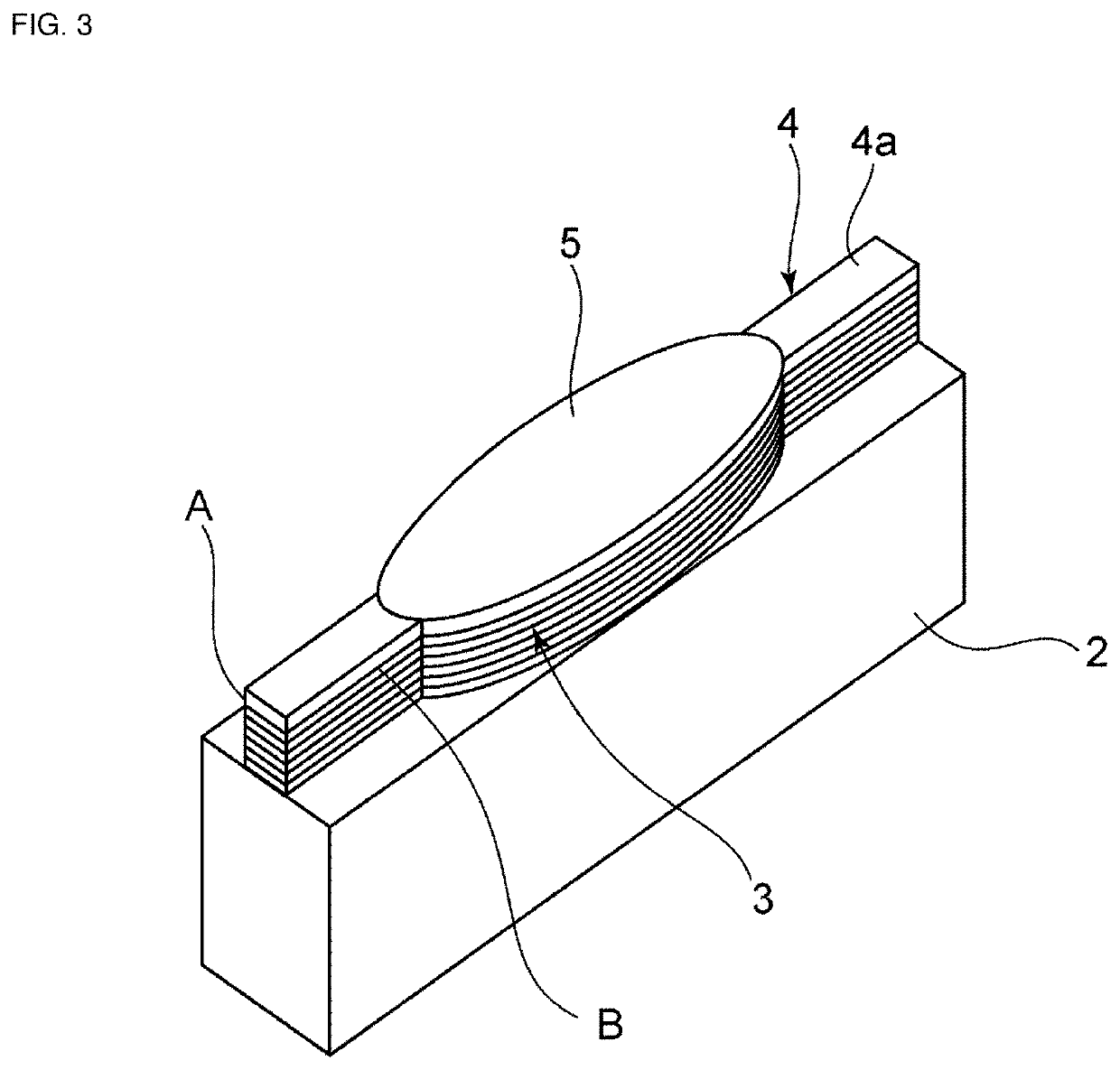
[0042]An acoustic wave device 1 includes a support substrate 2. A resonator 7 is disposed on the support substrate 2. The resonator 7 includes an acoustic-layer laminated body 3, a piezoelectric body 4, and first and second electrodes 5 and 6.

[0043]The acoustic-layer laminated body 3 includes a plurality of acoustic layers 3a to 3f. In the present preferred embodiment, the plurality of acoustic layers are laminated such that the acoustic layers 3a, 3c, and 3e that are low-acoustic-impedance layers each having a relatively low acoustic impedance and the acoustic layers 3b, 3d, and 3f that are high-acoustic-impedance layers each having a relatively high acoustic impedance are alternately laminated together. The resonator 7 includes the piezoelectric body...

second preferred embodiment

[0069]In a second preferred embodiment of the present invention, LiNbO3 is used as the piezoelectric body 4 illustrated in FIG. 1, whereas LiTaO3 is used in the first preferred embodiment. The remainder of the configuration of the acoustic wave device of the second preferred embodiment is the same as or similar to that of the acoustic wave device of the first preferred embodiment. Accordingly, the description of the structure of the acoustic wave device of the second preferred embodiment will be omitted by incorporating the description of the structure of the acoustic wave device 1 of the first preferred embodiment and the descriptions of the other portions.

[0070]In the acoustic wave device of the second preferred embodiment, as LiNbO3, θ of Euler angles (about 0°, θ, about 0°) and φ of Euler angles (about 0°, about −100°, φ) were varied so as to determine the impedance ratio of the resonator was determined. The impedance ratio of the resonator in the case of varying θ of the Euler ...


PUM


Abstract

An acoustic wave device includes a support substrate, a piezoelectric body including LiTaO3, a first electrode on a first main surface of the piezoelectric body, a second electrode on a second main surface, an acoustic-layer laminated body between a support substrate and the piezoelectric body. The azimuth angle of the piezoelectric body is (about 85° to 95°, about 85° to 95°, about 5° to 65°) represented in Euler angles.

Description

CROSS REFERENCE TO RELATED APPLICATIONS[0001]This application claims the benefit of priority to Japanese Patent Application No. 2019-067024 filed on Mar. 29, 2019 and is a Continuation Application of PCT Application No. PCT / JP2020 / 010294 filed on Mar. 10, 2020. The entire contents of each application are hereby incorporated herein by reference.BACKGROUND OF THE INVENTION1. Field of the Invention[0002]The present invention relates to an acoustic wave device including a support substrate, an acoustic layer, and a piezoelectric body that are laminated together.2. Description of the Related Art[0003]In the related art, various acoustic wave resonators that use bulk waves have been proposed. In an acoustic wave resonator described in Japanese Unexamined Patent Application Publication No. 2015-228620, a piezoelectric body is laminated on an acoustic multilayer film. The operation of the acoustic wave resonator at a higher frequency is achieved by reducing the thickness of the piezoelectri...

Claims


Application Information

Patent Timeline
Patent Type & Authority Applications(United States)
IPC IPC(8): H03H9/02H03H9/13
CPCH03H9/02157H03H9/02015H03H9/131H03H9/17
Inventor KADOTA, MICHIOTANAKA, SHUJI
Owner MURATA MFG CO LTD
Why Eureka
Try Eureka