

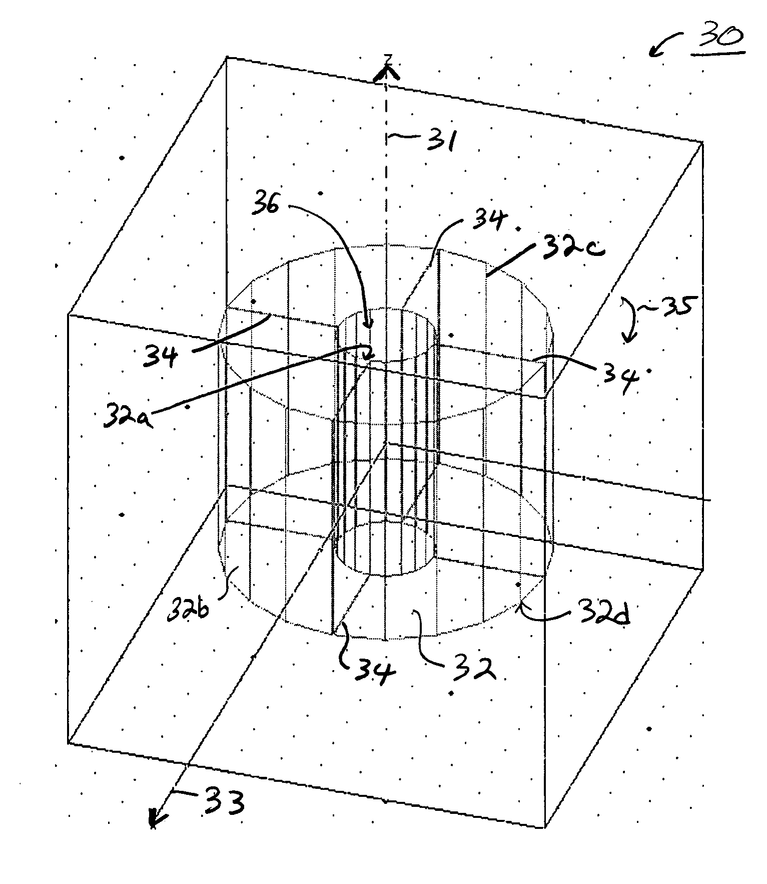
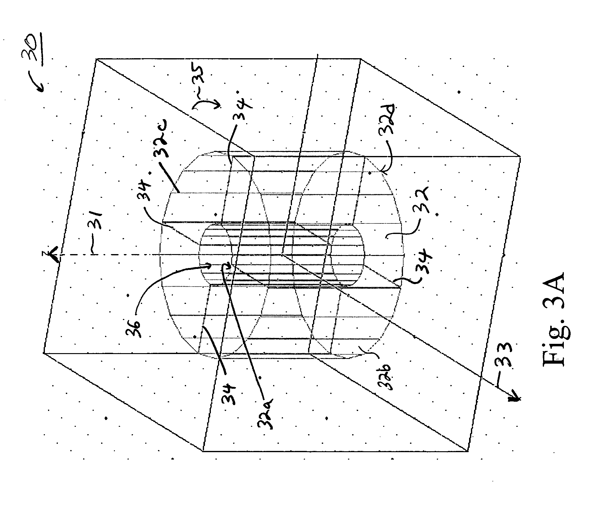
Slotted dielectric resonators and circuits with slotted dielectric resonators
a dielectric resonator and dielectric resonator technology, applied in the field of dielectric resonators, can solve the problems of reducing affecting the operation and the field decaying rapidly outside, so as to increase the center frequency of the resonator, the size of the resonator puck might be enlarged, and the width of the slit significantly affects the operation
- Summary
- Abstract
- Description
- Claims
- Application Information
AI Technical Summary
Benefits of technology
Problems solved by technology
Method used
Image

Examples
examples
[0082]FIGS. 7 through 17 show the results of computer simulations designed to demonstrate the effects and benefits of the incorporation of slits into dielectric resonators circuits in accordance with the principles of the present invention.
[0083]FIG. 7A is a transparent isometric view of a conventional, single-pole dielectric resonator circuit model with the given dimensions and wherein the dielectric resonator is formed of a material having an ε of 45. Computer simulations were run on this model. The fundamental mode in this simulation was the TE mode at 1.149 GHz. This circuit had a Q of 36,000 for the fundamental mode.
[0084] The loss tangent was 0.000027 and its inverse (which gives another definition for Q) was, as expected, 37,000. This demonstrates that the losses in the circuit are dielectric losses. The next lowest mode was the first hybrid mode, H11. It has two polarizations with two slightly different corresponding frequencies. The next lowest mode was the TM mode.
[0085...
PUM
 Abstract
Description
Claims
Application Information