Nonreciprocal circuit device

a circuit device and non-reciprocal technology, applied in waveguide devices, basic electric elements, electrical apparatus, etc., can solve the problem of limited improvement of the insertion loss of the 2-port type isolator, and achieve the effect of reducing the insertion loss and increasing the q value of the second central electrod

Active Publication Date: 2010-03-16
MURATA MFG CO LTD
View PDF4 Cites 0 Cited by
  • Summary
  • Abstract
  • Description
  • Claims
  • Application Information

AI Technical Summary

Benefits of technology

[0009]To overcome the problems described above, preferred embodiments of the present invention provide a nonreciprocal circuit device that reduces an insertion loss and increases the Q value of a second central electrode.
[0011]The nonreciprocal circuit device is preferably a 2-port type lumped constant isolator having an intrinsically small insertion loss with the first central electrode and the second central electrode arranged to cross each other on a substantially rectangular parallelepiped ferrite in an electrically insulated state from each other. In particular, the second central electrode is provided by winding the electrode layer around the ferrite by at least about three turns. The width dimension of the electrode layer wound as the outermost winding of the second central electrode is set to be greater than the width dimension of the electrode layer wound as the inner winding of the second central electrode. This arrangement increases the Q of the second central electrode, thereby leading to a reduced insertion loss.
[0012]The electrode layer of the second central electrode wound as the outermost winding of the second central electrode preferably expands outwardly. The width dimension of the electrode layer is increased at a high space efficiency without damaging the insulation.
[0015]Thus, various preferred embodiments of the present invention provide a nonreciprocal circuit device with an increased Q value of a second central electrode and a reduced insertion loss.

Problems solved by technology

In other words, in the known 2-port type isolator including the electrode layer defining the second central electrode wound around the ferrite by a plurality of turns, the line width of the second central electrode is relatively small, and the improvement of the insertion loss of the 2-port type isolator is limited.

Method used


Image

  • Nonreciprocal circuit device
  • Nonreciprocal circuit device
  • Nonreciprocal circuit device

Examples


Embodiment Construction

[0026]Nonreciprocal circuit devices according to preferred embodiments of the present invention are described below with reference to the accompanying drawings.

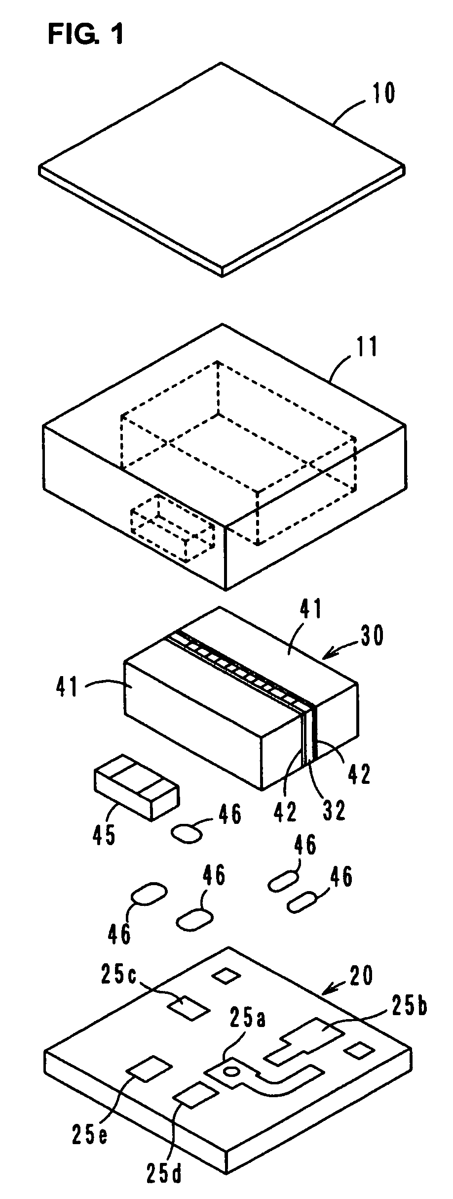
[0027]FIG. 1 is an exploded perspective view of a 2-port type isolator as an example of the nonreciprocal circuit device according to a preferred embodiment of the present invention. The 2-port type isolator is a lumped constant type isolator, and includes a ferrite-magnet assembly 30 primarily including a plate yoke 10 which defines a shield member, a sealing resin 11, a circuit board 20, a ferrite 32, and permanent magnets 41. FIG. 1 further shows a chip resistor 45 and connection solder 46, defining a circuit to be discussed below.

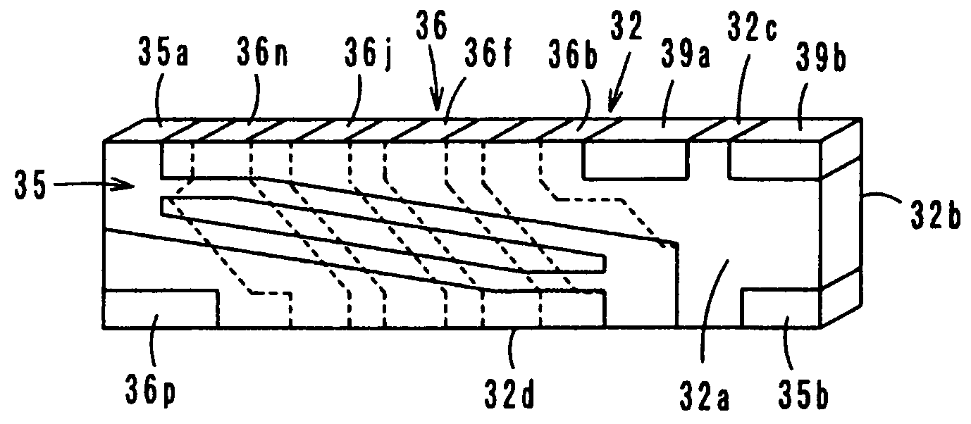
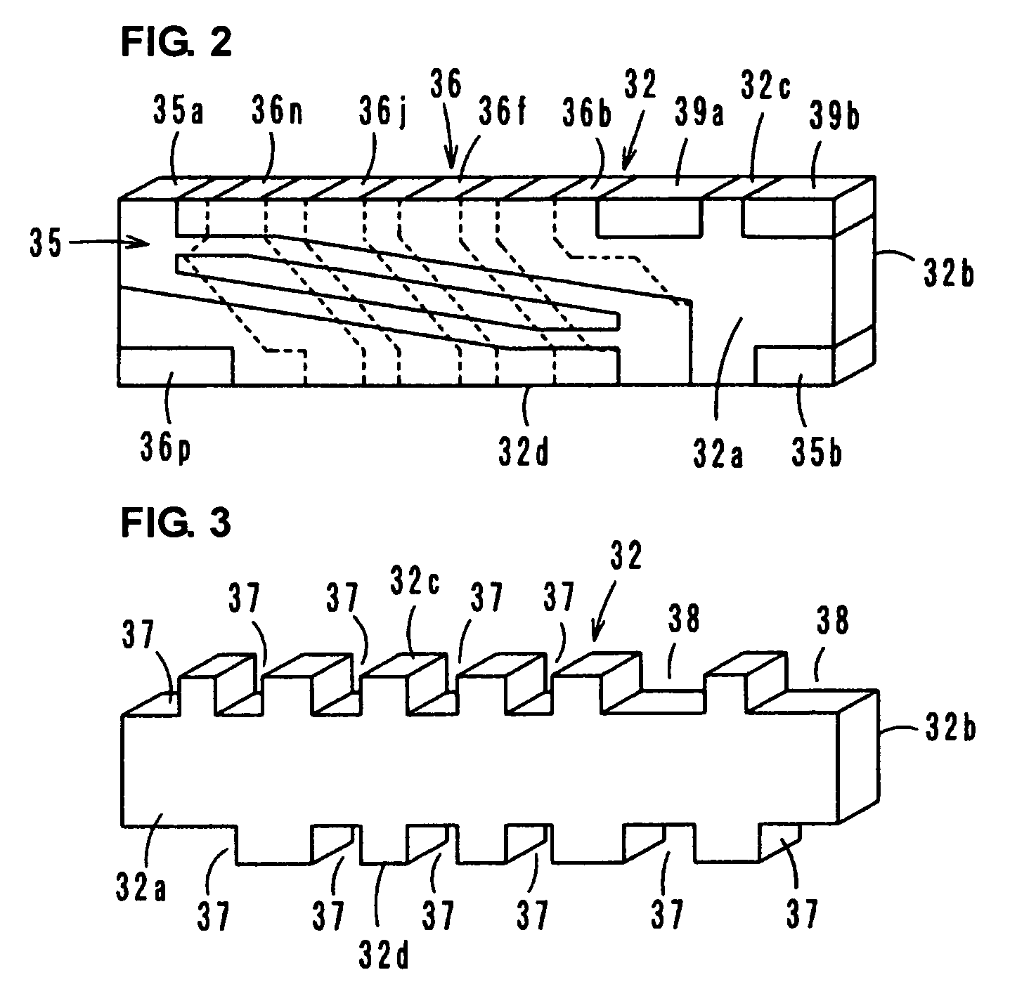
[0028]With reference to FIGS. 2 and 4A to 4E, a first central electrode 35 and a second central electrode 36, electrically insulated from each other, are provided on front and back main surfaces 32a and 32b of the ferrite 32. Here, the ferrite 32 has a substantially rectangular parallelepiped sha...


PUM


Abstract

A nonreciprocal circuit device includes a permanent magnet, a ferrite to which the permanent magnet applies a direct-current magnetic field, first and second central electrodes arranged on the ferrite, and a circuit board. The first central electrode includes electrode layers provided on main surfaces of the ferrite connected by an electrode provided on a top surface of the ferrite. A second central electrode includes electrode layers provided on the main surfaces of the ferrite connected by electrodes arranged on top and bottom surfaces of the ferrite. The second electrode is wound at least about three turns around the ferrite. A width dimension of the outermost electrode layers of the second central electrode is greater than a width dimension of the inner electrode layers of the second central electrode.

Description

BACKGROUND OF THE INVENTION[0001]1. Field of the Invention[0002]The present invention relates to a nonreciprocal circuit device and, in particular, to a nonreciprocal circuit device such as an isolator or a circulator used in microwave bands.[0003]2. Description of the Related Art[0004]A nonreciprocal circuit device, such as an isolator or a circulator, has known characteristics that transmit a signal only in a predetermined direction and not in a reverse direction. Because of these characteristics, for example, the isolator is used in a transmitter circuit of a mobile communication device, such as an automobile telephone or a cellular phone, for example.[0005]A 2-port isolator is described as a known nonreciprocal circuit device in International Publication No. 2007 / 046229. In the 2-port isolator, a first central electrode is wound by one turn around a rectangular parallelepiped ferrite and a second central electrode is wound by a plurality of turns around the ferrite such that the...

Claims


Application Information

Patent Timeline
Patent Type & Authority Patents(United States)
IPC IPC(8): H01P1/36
CPCH01P1/387
Inventor KAWANAMI, TAKASHINAKAJIMA, REIJI
Owner MURATA MFG CO LTD
Why Eureka
Try Eureka