Method and mechanism for tuning dielectric resonator circuits

a dielectric resonator and circuit technology, applied in the direction of bridges, scaffold accessories, building scaffolds, etc., can solve the problems of rare, if ever, use, tedious and laborious, and often consume weeks, so as to reduce the loss of insertion and improve the effect of q

Inactive Publication Date: 2005-09-15
MA COM
View PDF43 Cites 2 Cited by
  • Summary
  • Abstract
  • Description
  • Claims
  • Application Information

AI Technical Summary

Benefits of technology

[0021] The invention comprises a technique and associated mechanisms for implementing the technique by which dielectric resonator circuits, such as filters, can be tuned in both frequency and bandwidth without the need for irises, tuning screws, and / or tuning plates. This helps to substantially reduce insertion loss and improve Q in the circuit because of the elimination of conductive components within the fields of the dielectric resonators.

Problems solved by technology

There are additional higher order modes, including the TM01 mode, but they are rarely, if ever, used and essentially constitute interference.
Typically, all of the modes other than the TE mode (or H11 mode in filters that utilize that mode) are undesired and constitute interference.
Bandwidth tuning by adjusting the irises, tuning screws, and cavity is, largely, a process of trial and error and is tedious and labor-intensive and often consumes weeks.
Thus, the machining process itself is expensive and error-prone.
Furthermore, the walls within which the irises are formed, the tuning screws and even the cavity all create losses to the system, decreasing the quality factor, Q, of the system and increasing the insertion loss of the system.
Thus, while the iris walls and tuning screws are necessary for tuning, they are the cause of loss of energy within the system.
Another disadvantage of the use of tuning screws within the irises is that such a technique does not permit significant changes in coupling strength between the dielectric resonators.
It would be very difficult using tuning screws to adjust the bandwidth of the signal to much greater than 21 or 22 MHz.
Even furthermore, it is difficult to implement cross-coupling between multiple dielectric resonators using the aforementioned conventional tuning techniques.

Method used


Image

  • Method and mechanism for tuning dielectric resonator circuits
  • Method and mechanism for tuning dielectric resonator circuits
  • Method and mechanism for tuning dielectric resonator circuits

Examples


first embodiment

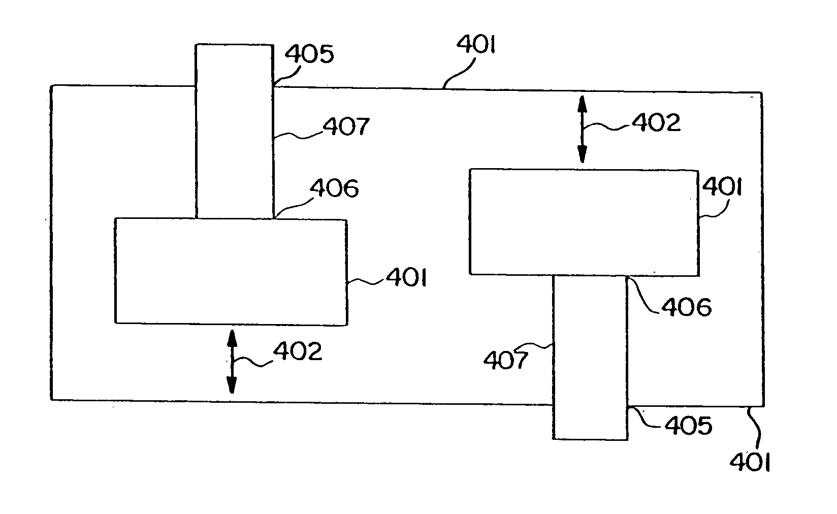
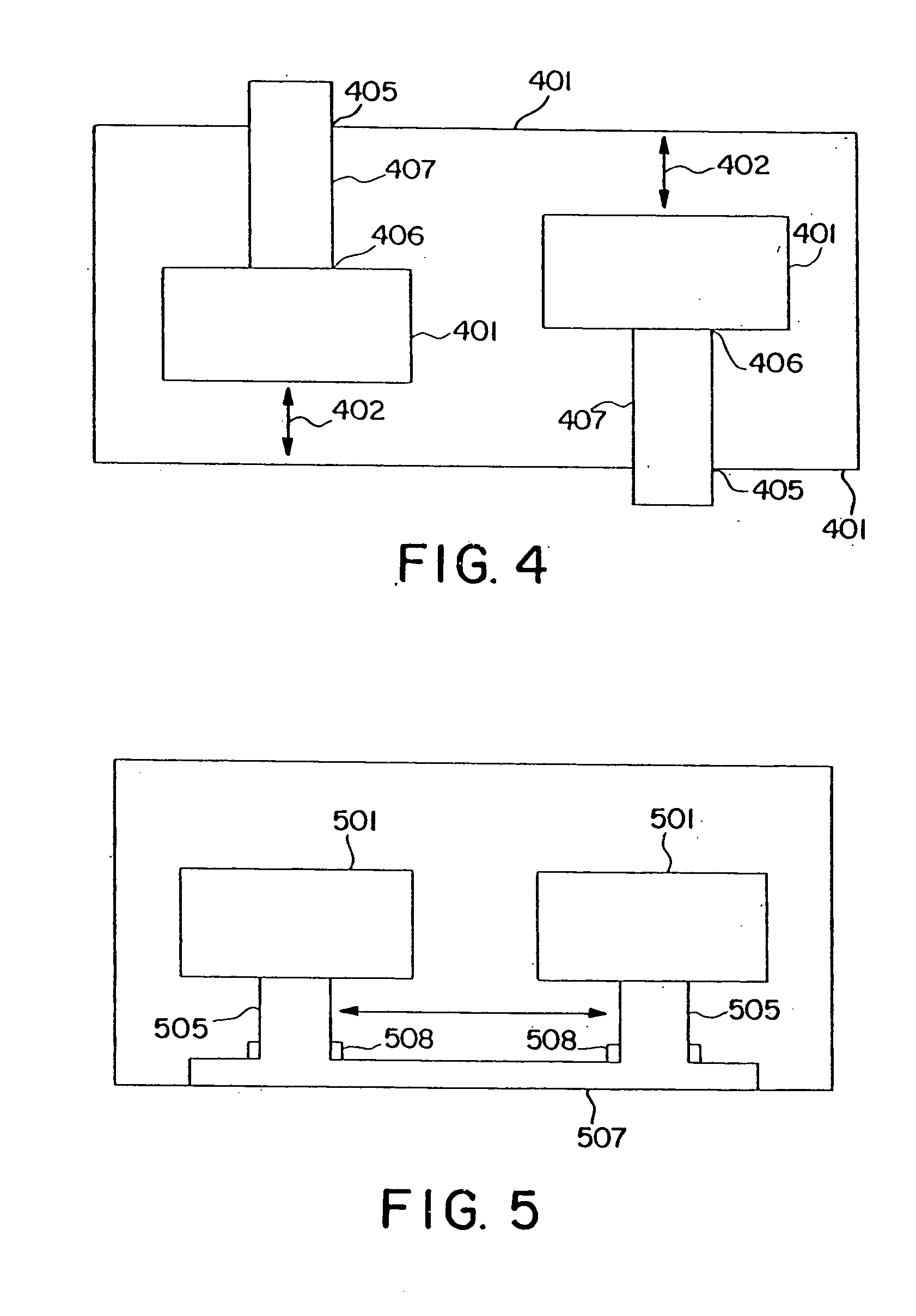
[0046]FIG. 4 illustrates the present invention. In this embodiment, the dielectric resonators that electromagnetically couple to each other are vertically adjustable relative to each other. In the context of this application, the term “vertically” refers to the dimension along the longitudinal axis of the dielectric resonators or, alternatively, the direction perpendicular to the lines of the TE mode. Thus, for instance, in FIG. 4, the dielectric resonators 401 are adjustable in the direction of the arrows 402. Many mechanisms could be used to provide the longitudinal adjustability that would be apparent to those of ordinary skill in this art. One particular mechanism would be to mount the dielectric resonator 401 on holding posts, and preferably screws 407, which are screwed into threaded holes 405 in walls 401 of the enclosure. Alternately, the holes 405 can be blind holes. The resonators 403 also may be adjustably mounted on the screws 407. Particularly, the longitudinal central ...

second embodiment

[0051]FIG. 5 illustrates the invention in which the resonators are horizontally adjustable relative to each other. Horizontal adjustability can be provided by any reasonable means. FIG. 5 illustrates embodiment in which the resonators 501 are mounted on posts 505 which, in turn, are mounted on a resonator holder 507. The holder may include one or more slots within which the posts 505 are engaged. The posts may mate with the slots with a frictional fit. Alternatively, the bottoms of the support posts may have radial gears which form a gear assembly with mating gears in the slot. Even more simply, the bottoms of the posts 505 may be threaded and held tightly to the slots by nuts and / or lock washers 508 that can be selectively tightened. When loosened, the posts 505 can move within the slots. When tightened, they become fixed within the slots. Any other reasonable mechanical connection mechanism that allows the posts to slide horizontally and, preferably, then locked in position would ...


PUM


Abstract

The invention comprises a technique and associated mechanisms by which dielectric resonator circuits, such as filters, can be tuned in both frequency, bandwidth or both without the need for irises, tuning screws and / or tuning plates. In accordance with the invention, the positions of the dielectric resonators are adjustable relative to each other within the cavity in multiple ways, including vertically and horizontally. The dielectric resonators also may tilt relative to each other. Furthermore, an off-center longitudinal hole can be machined in one or more of the dielectric resonators so as to make the electromagnetic field of the resonator non-uniform so that the dielectric resonator can be rotated about its longitudinal axis to alter the coupling between dielectric resonators. In accordance with another aspect of the invention, frequency tuning can be accomplished by using two separate dielectric resonators adjacent each other, one on top of the other, and adjusting the vertical spacing therebetween to achieve the desired center frequency within that dielectric resonator pair.

Description

FIELD OF THE INVENTION [0001] The invention pertains to dielectric resonator circuits and, particularly, dielectric resonator filters. More particularly, the invention pertains to techniques for tuning such circuits in bandwidth and in frequency. BACKGROUND OF THE INVENTION [0002] Dielectric resonators are used in many circuits for concentrating electric fields. They are commonly used as filters in high frequency wireless communication systems, such as satellite and cellular communication applications. They can be used to form oscillators, triplexers and other circuits, in addition to filters. [0003]FIG. 1 is a perspective view of a typical dielectric resonator of the prior art. As can be seen, the resonator 10 is formed as a cylinder 12 of dielectric material with a circular, longitudinal through hole 14. FIG. 2 is a perspective view of a microwave dielectric resonator filter 20 of the prior art employing a plurality of dielectric resonators 10. The resonators 10 are arranged in th...

Claims


Application Information

Patent Timeline
Patent Type & Authority Applications(United States)
IPC IPC(8): H01P1/20H01P1/208H01P7/10
CPCH01P1/2084E01D22/00E04G3/24E04G5/10E04G5/14
Inventor PANCE, KRISTI DHIMITERCHANNABASAPPA, ESWARAPPA
Owner MA COM
Why Eureka
Try Eureka