Heads-up display apparatus

a display apparatus and head-up technology, applied in the field of head-up display apparatus, can solve the problems of affecting the use of smart glasses, affecting the use of glasses, so as to reduce the size of the optics, reduce optical distortion, and remove image distortion

Pending Publication Date: 2022-01-20
BUILDVATION PTY LTD
View PDF0 Cites 0 Cited by
  • Summary
  • Abstract
  • Description
  • Claims
  • Application Information

AI Technical Summary

Benefits of technology

[0024]Preferably, the electronic display comprises a liquid crystal display (LCD). Preferably, the LCD is approximately 12 mm in height and 24 mm in length to reduce the size of the optics required.
[0025]Preferably, the lens is located adjacent to the mirror and is suitably located between the mirror and the half-silvered mirror. Preferably, the lens is configured for the distance between the digital display and the lens, and the lens and an eye of a user to reduce optical distortion and to allow the entire display to be viewed from a typical distance between the eye and the lens.
[0026]Preferably, the half-silvered or pellicle mirror comprises a semi-transparent mirror or one-way mirror, wherein a mirrored surface of the half-silvered mirror is facing the lens to remove image distortion caused by reflection from a transparent substrate in front of the mirrored surface.

Problems solved by technology

Such mistakes could be dangerous for the user or others in the area.
However, these displays are often mounted on the side of a surgeon's or user's head (as they would obstruct the view if placed in front of their face) and require the surgeon or user to glance away from the patient or task to refer to the display.
This can be distracting and may lead to mistakes due to distraction.
However, these smart glasses can be difficult to use (such as with prescription glasses, for example), are fragile and include complex componentry with short battery life.

Method used


Image

  • Heads-up display apparatus
  • Heads-up display apparatus
  • Heads-up display apparatus

Examples


Embodiment Construction

[0045]The following disclosure relates to a display and display device for mounting to headgear, such as a helmet, to display user-relevant digital information.

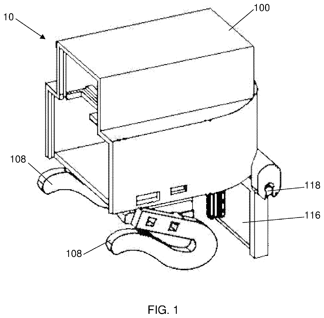
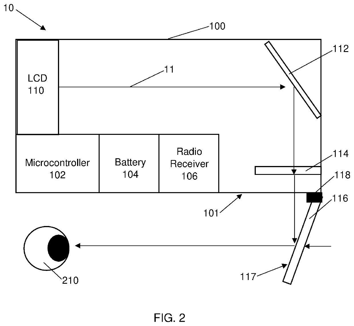
[0046]FIGS. 1 and 2 illustrate an embodiment of a heads-up display apparatus 10 to be mounted on headgear or a helmet 2 (as shown in FIG. 4).

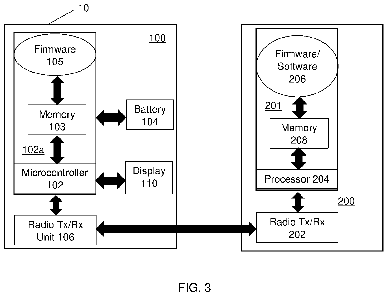
[0047]The heads-up display apparatus 10 includes a housing 100 which houses a display controller in the form of a microcontroller 102, a battery 104 and a radio receiver 106 (which can be seen in FIGS. 2 and 3 and is explained below).

[0048]The housing 100 is a small waterproof (and preferably ingress protection 67 rated) box with a mounting bracket in the form of a clamp 108 that is suitable to clip onto headgear. The type of clip can be varied or interchanged to suit the type of hat or headgear being worn (for example, a small spring loaded or bolt clamp to attach to the brim of a construction hard hat).

[0049]Referring to FIGS. 2 and 3, the microcontroller 102 operates and controls the ...


PUM


Abstract

A heads-up display apparatus adapted to be mounted to a helmet or item of headgear to display an image to a user includes a housing and an image projection system. The image projection system includes an electronic display, a display controller adapted to receive and process data presented on the electronic display, an aspherical lens, a semi-transparent display panel locatable in a line of sight of a user, and a front surface mirror for reflecting light emitted from the electronic display through the aspherical lens onto the semi-transparent display panel. The electronic display, the aspherical lens and the front surface mirror are arranged within the housing, and the heads-up display apparatus minimises refocusing of an eye of a user when looking from a primary task to the display and back to the primary task.

Description

CROSS-REFERENCE TO RELATED APPLICATIONS[0001]This application is related to and claims priority from earlier filed PCT Patent Application No. PCT / AU2019 / 051272, filed 19 Nov. 2019, and earlier filed Australian Patent Application No. 2018904419, filed 19 Nov. 2018.BACKGROUND[0002]The present disclosure relates to a heads-up display. In particular, embodiments of an invention disclosed herein relate to a heads-up display apparatus that can be mounted to a user's head or headgear and provide unobtrusive display in the field of view of the user.[0003]Reference to background art herein is not to be construed as an admission that such art constitutes common general knowledge.[0004]Some tasks, ranging from surgery to running to driving to construction and mining, require a user to remain focused on a task without moving their hands and / or eyes away from the task lest an accident or mistake occur. Such mistakes could be dangerous for the user or others in the area.[0005]Displays incorporate...

Claims


Application Information

Patent Timeline
Patent Type & Authority Applications(United States)
IPC IPC(8): G02B27/01G02B27/30G02B3/04
CPCG02B27/0172G02B27/30G02B2027/011G02B27/0149G02B2027/014G02B3/04G02B2027/0198G02B2027/0141G02B2027/0127G02B2027/0156
Inventor KUIPER, ALEXDOBSON, DEANBEDGOOD, THOMAS
Owner BUILDVATION PTY LTD
Why Eureka
Try Eureka