Determining the engagement point of a clutch

Inactive Publication Date: 2022-01-27
ZF FRIEDRICHSHAFEN AG
View PDF1 Cites 0 Cited by
  • Summary
  • Abstract
  • Description
  • Claims
  • Application Information

AI Technical Summary

Benefits of technology

The patent describes a method for accurately determining the engagement point of a clutch in a motor vehicle transmission. This is important for ensuring proper functioning of the vehicle's transmission and reducing wear on the clutch and acceleration device. The method involves selectively accelerating one side of the clutch using an acceleration device to prevent the clutch from moving during the engagement point determination. The acceleration device increases the frictional forces within the clutch to prevent movement. By controlling the acceleration device, the method can be used with different types of transmissions and clutches, and can be easily integrated into existing drive-trains. The engagement point is determined without measuring the drag torque of the transmission, which simplifies the method. The technical effect of this method is to ensure accurate engagement point determination and improve the performance and durability of motor vehicles' transmissions.

Problems solved by technology

However the engagement point of a clutch varies, in particular because of component tolerances and clutch wear.
Not every procedure for determining the engagement point is suitable for any installation position, structure and operating method of an automatic clutch.
Such a movement can also be caused by vibrations or other external influences—even when the clutch is positioned horizontally.
If that happens during the ‘learning’ of the engagement point, there is a risk that the engagement point will be determined erroneously.
The result of this is that the clutch cannot be operated automatically in the correct manner.

Method used


Image

  • Determining the engagement point of a clutch

Examples


Embodiment Construction

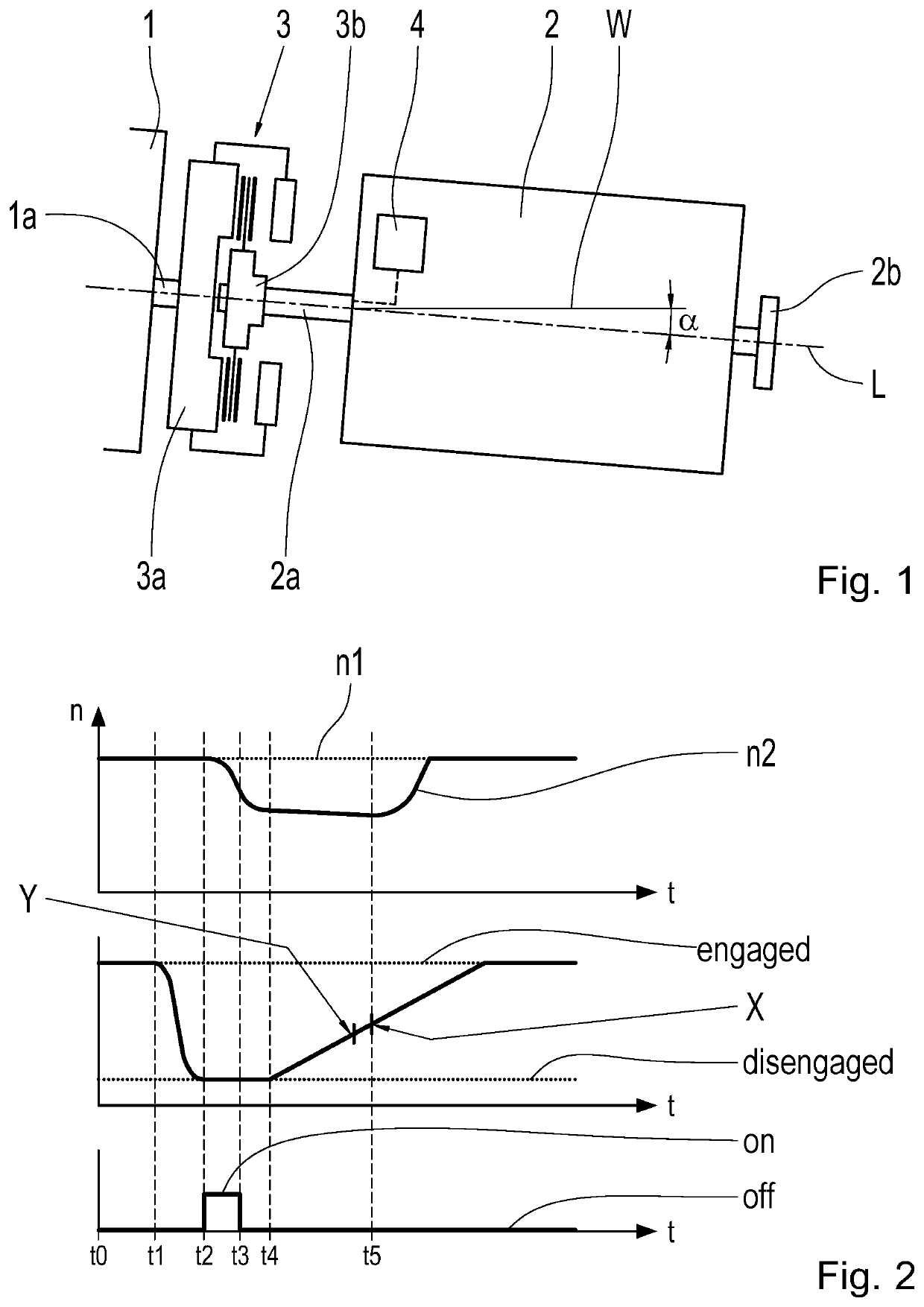
[0044]According to FIG. 1 the drive-train of a motor vehicle comprises a drive motor 1, in particular such as an internal combustion engine for propelling the motor vehicle. In addition a multi-stage transmission 2 is provided in the drive-train. In this case it can be an automated change-speed transmission but it can also be an automatic transmission. The transmission 2 has an output shaft 2b on its drive output side, by means of which further drive-output-side components of the drive-train are rotationally coupled. Thus, in a manner already known as such, for example wheels of the motor vehicle can be driven by means of the drive motor 1. On the input side, the transmission 2 has a drive input shaft 2a. In particular the transmission 2 has a low drag torque, so its internal frictional torques are relatively low. Accordingly, the input and output shafts 2a, 2b can be rotated particularly easily.

[0045]A frictional clutch 3 is drive-technically connected between the drive motor 1 and...


PUM


Abstract

A method for determining an engagement point (X) of a clutch (3). The clutch (3) has first and second clutch sides (3a, 3b), which are rotationally decoupled when the clutch (3) is disengaged / open and which are rotationally coupled when the clutch (3) is engaged / closed. The method includes the steps of disengaging the clutch (3) and then engaging the clutch (3), in order to determine the engagement point (X). During this, the first clutch side (3a) is driven in rotation and the second clutch side (3b) is accelerated, for at least part of the time, by an acceleration device (4). A control device actuates the clutch (3) in order determine the engagement point (X) of the clutch (3), and a computer program product with stored commands, brings about the sequence of the method when the program is operated on a suitable control unit.

Description

[0001]This application is a National Stage completion of PCT / EP2019 / 083792 filed Dec. 5, 2019, which claims priority from German patent application serial no. 10 2018 221 532.4 filed Dec. 12, 2018.FIELD OF THE INVENTION[0002]The invention relates to a method for determining an engagement point of a clutch, in particular a frictional clutch. It also relates to a control unit designed for the purpose and to a computer program product with commands for carrying out the method.BACKGROUND OF THE INVENTION[0003]Clutches are known which are actuated automatically, i.e. opened and closed by a clutch actuator, for example in automatic or automated motor vehicle transmissions. For the automatic actuation of a clutch, knowledge of the so-termed engagement point of the clutch is of prime importance. The engagement point is understood to mean that clutch position at which the clutch components of the clutch that can be coupled with one another are only just in contact with one another without th...

Claims


Application Information

Patent Timeline
IPC IPC(8): F16D48/06
CPCF16D48/06F16D2500/10412F16D2500/1045F16D2500/30415F16D2500/50266F16D2500/3127F16D2500/1064F16D2500/1085F16D2500/3026F16D2500/30428F16D2500/1066F16D2500/50245F16D2500/50251F16D2500/70605F16D2500/5012
Inventor GANSOHR, MARCUSSCHNEIDER, MANUELWAGEGG, MARCO
Owner ZF FRIEDRICHSHAFEN AG
Why Eureka
Try Eureka