
Torque converter

a torque converter and axial direction technology, applied in the direction of rotary clutches, fluid couplings, gearings, etc., can solve the problems of difficult to avoid the increase in size caused by the dimension of the torque converter extending in an axial direction, and achieve the effect of securing the torque ratio performance and efficient arrangement of the damper elemen

Active Publication Date: 2022-01-27
JATCO LTD +1
View PDF6 Cites 1 Cited by
  • Summary
  • Abstract
  • Description
  • Claims
  • Application Information

AI Technical Summary

Benefits of technology

The patent text discusses the challenges faced by downsized turbocharged engines in vehicles and how they impact the torque converter. The text suggests using a torus with a suitable flatness ratio, thinness ratio, and inner diameter ratio to achieve both size and performance factors. This allows for an efficient arrangement of the damper element and securing of the torque ratio performance. The technical effect of this approach is improved efficiency and performance of the vehicle's torque converter.

Problems solved by technology

As a result, in this case, in addition to the point that a damper element of high attenuation is necessary, by using a large torus, the increase in size caused by the dimension of the torque converter extending in an axial direction becomes difficult to avoid.

Method used


Image

  • Torque converter
  • Torque converter
  • Torque converter

Examples


Embodiment Construction

[0020]An embodiment of the present invention will be described below with reference to the accompanying drawings.

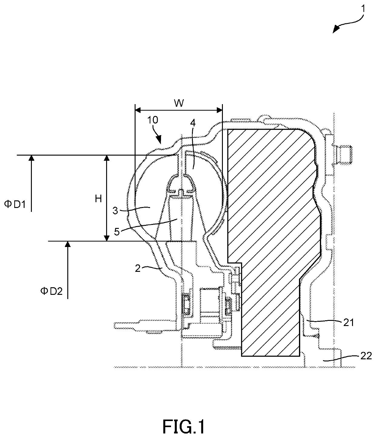
[0021]FIG. 1 is a schematic diagram of a torque converter 1. FIG. 1 illustrates essential parts of the torque converter 1 in a cross section. The torque converter 1 includes a cover 2, a pump impeller 3, a turbine runner 4, and a stator 5.

[0022]The cover 2 is connected to an engine not illustrated. The cover 2 is configured having a front cover 21, and constitutes a casing of the torque converter 1. A cylindrical shaft 22 is fixed on an inner side in a radial direction of the front cover 21.

[0023]The cover 2 houses the pump impeller 3, the turbine runner 4, and the stator 5. The pump impeller 3 is provided on the cover 2. The turbine runner 4 is arranged facing the pump impeller 3, and is connected to an output shaft. The stator 5 is arranged between the pump impeller 3 and the turbine runner 4.

[0024]The torque converter 1 has a torus 10. The torus 10 is a flow path space...


PUM


Abstract

A torque converter has a torus. The torus has a size set based on a flatness ratio obtained by dividing a width of the torus in an axial direction by a width of the torus in a radial direction, a thinness ratio obtained by dividing the width of the torus in the axial direction by an outer diameter of the torus, and an inner diameter ratio obtained by dividing an inner diameter of the torus by the outer diameter of the torus.

Description

TECHNICAL FIELD[0001]The present invention relates to a torque converter and a setting method for a torque converter.BACKGROUND ART[0002]JP2018-9632A discloses a torque converter for holding down dimensions in an axial direction.SUMMARY OF INVENTION[0003]In recent years, approaches have been made in vehicles to implement downsized turbocharged engines. The downsized turbocharged engines are advantageous in fuel economy, however gives the following effects on the torque converter. Namely, the downsized turbocharged engines cause an increase in fluctuation of input torque from the engine due to the reduction in the number of cylinders. Moreover, the input torque from the engine decreases upon starting, since the engine operating state upon starting is in a non-turbocharged region or in a transient state to a turbocharged region.[0004]In order to hold down the fluctuation in the input torque, a damper element of high attenuation is necessary. Moreover, in order to compensate for the de...

Claims


Application Information

Patent Timeline
IPC IPC(8): F16H41/26
CPCF16H41/26F16H45/02F16D33/20
Inventor KAWASHIMA, KAZUNORI
Owner JATCO LTD
Learn More