Integral magnet mount for golf ranging device

a golf laser rangefinder and magnet mount technology, which is applied in the field of integrated magnet mounts for golf rangefinders, can solve the problems of significant elevation differences between the golf ball striking location and the landing spot, and the laser range finders originally had significant problems discriminating trees and other objects, so as to facilitate the holding of the golf laser rangefinder, facilitate the alignment, and reduce the likelihood of damage to sensitive internal components

Inactive Publication Date: 2022-01-27
BUSHNELL
View PDF0 Cites 0 Cited by
  • Summary
  • Abstract
  • Description
  • Claims
  • Application Information

AI Technical Summary

Benefits of technology

[0013]A feature and advantage of embodiments is a golf laser rangefinder comprising a housing and one or more magnets supported by the housing. The one or more magnets allow the golf laser rangefinder to be quickly stowed as magnetic force from the magnet fixes the golf laser rangefinder to a ferromagnetic object such as a portion of a golf cart. The one or more magnets allow the golf laser rangefinder to be stowed in a manner and location that makes the golf laser rangefinder readily accessible and visible immediately in front of the golfer, for example on an upright golf cart roof support rail.
[0014]A feature and advantage of embodiments is a golf laser rangefinder comprising a housing and a pair of magnets supported by the housing, the pair of magnets including a first magnet and a second magnet spaced apart from one another such that the magnets are positioned in opposing corners of a generally rectangular lateral side of the laser rangefinder housing. In embodiments, the distance between the first magnet and the second magnet maximized to provide greater mounting stability when the golf laser rangefinder is fixed to a ferromagnetic object such as a portion of a golf cart, for example a forward roof support member.
[0015]A feature and advantage of embodiments is a golf laser rangefinder comprising a housing and a pair of magnets supported by a side wall that includes a smooth outer surface for easy cleaning and for reducing the likelihood that debris will collected. In embodiments the housing arrangement minimizes component connection joints that can accumulate and trap dirt and debris. In embodiments, the side wall supporting the pair of magnets includes no grooves to collect debris.
[0016]A feature and advantage of embodiments is a golf laser rangefinder comprising a housing and a pair of magnets disposed along an orientation line arranged for locating the golf laser rangefinder at a predetermined orientation. In embodiments, the predetermined orientation is selected to reduce the likelihood that sensitive internal components will be damaged by radiation from the sun. In embodiments the magnets are aligned on a line extending between opposing corners of a generally rectangular lateral side wall of the laser rangefinder housing.
[0019]A feature and advantage of embodiments is a golf laser rangefinder including a housing with a lateral side that has a central screen and operating button as the periphery of the screen. This arrangement may facilitate holding the golf laser rangefinder in the palm of one hand and pushing the buttons with the other hand while viewing the screen. Magnets are positioned on the opposite lateral side, allowing the user to view the lateral side screen, operate the device, and then mount the device with the screen facing outwardly with the operator never taking his eyes off of the information provided on the screen. This can be advantageous as the display is giving a yardage readout that is changing as the golf cart approaches a ball location. Such also permits the golf cart occupant to keep his eyes forward while the cart is moving reducing any chance of a golf cart accident.
[0021]A feature and advantage of embodiments is that the golf laser rangefinder is be readily stowable so that it is out of the way when not needed. A feature and advantage of embodiments is that the golf laser rangefinder is readily accessible, so as to be quickly and easy retrieved from a stowed position saving time on the golf course and facilitating pace of play. A feature and advantage is that the magnets are permanently attached to the housing.

Problems solved by technology

Generally, the fairway is far from perfectly flat and may have significant undulations and changes in elevation, sometimes the elevation differential between the golf ball striking location and the landing spot, such as the green, can be significant.
Laser range finders originally had significant issues discriminating trees and other objects from the flagsticks.
Slow play can result by players taking too long to line up shots, considering which club to hit, assessing the many variables, such as wind, elevation differences, potential landing spots, and risks of off-line shots.

Method used


Image

  • Integral magnet mount for golf ranging device
  • Integral magnet mount for golf ranging device
  • Integral magnet mount for golf ranging device

Examples


Embodiment Construction

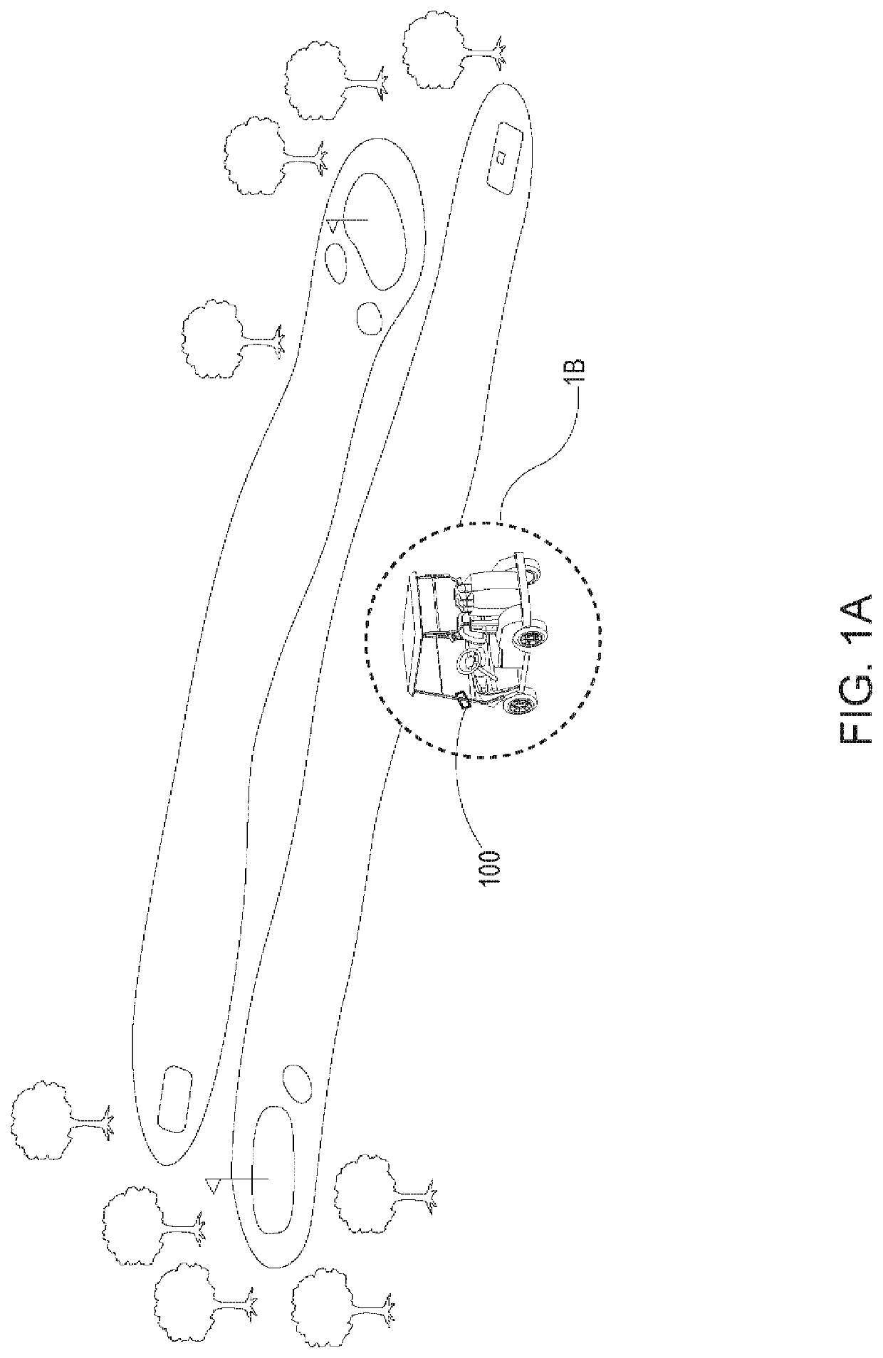
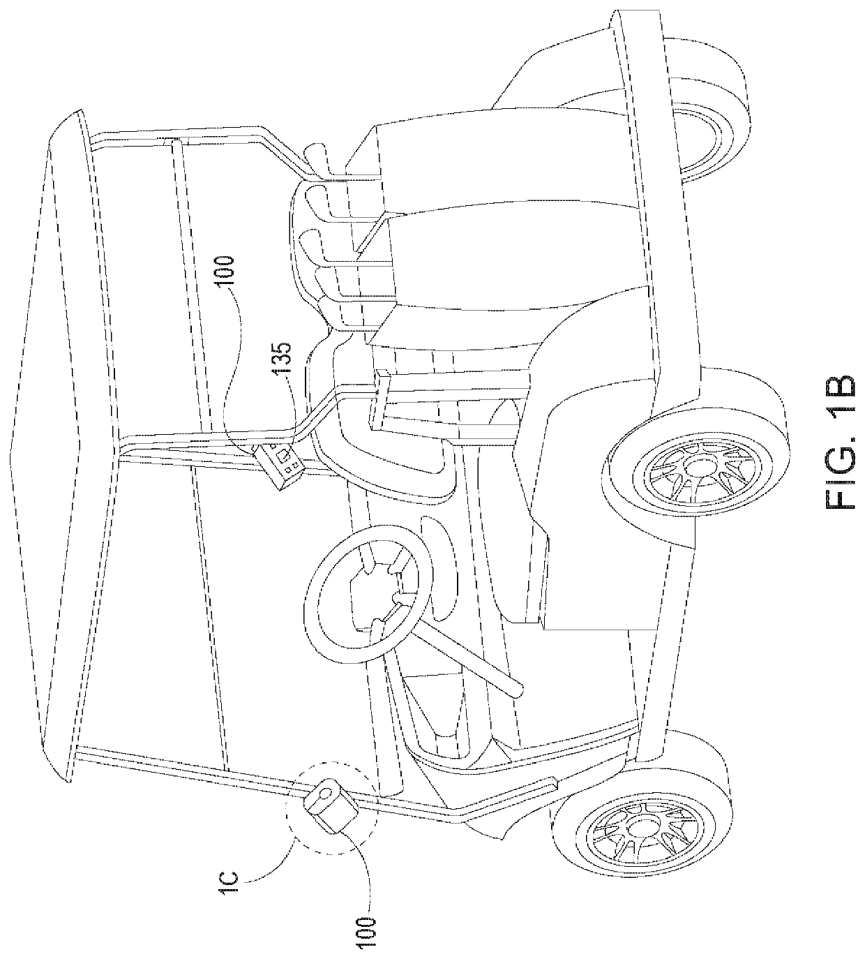
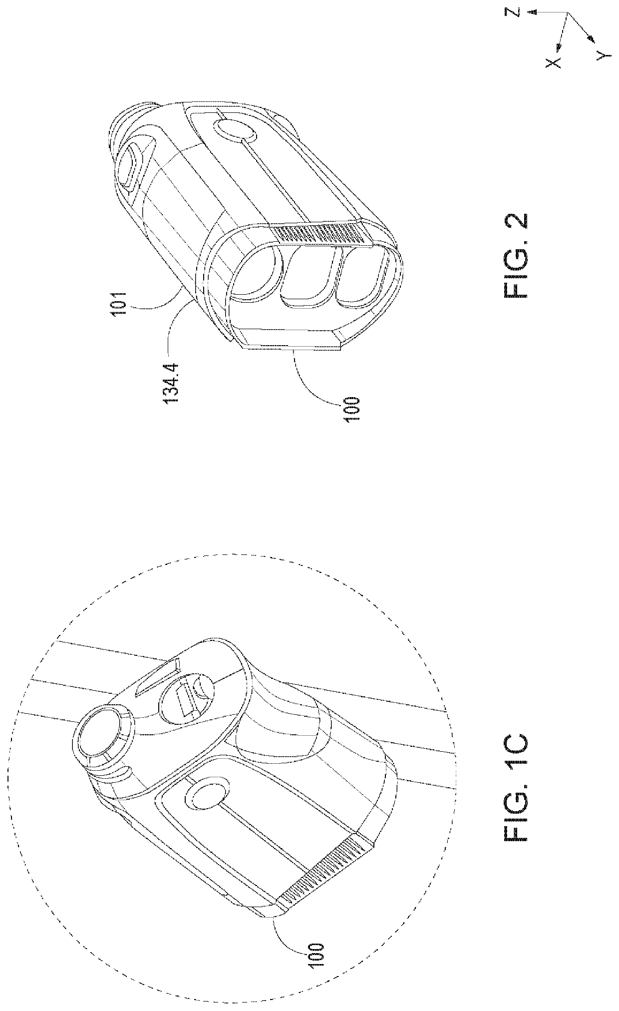
[0043]Referring to FIGS. 1A-2, a golf cart 90 with upright roof support members 92 removably receives a golf laser rangefinders 100 with a magnetic attraction regions 101. In embodiments, the golf laser rangefinder has a viewfinder, a push button laser actuator, an eyepiece, and a display viewable through the eyepiece with information and data provided on the display. The information includes a measured distance readout and may include additional information such as “play as” distance, battery information, hole being played information, distance to front of green, and distance to back of green.

[0044]Referring to FIGS. 1C to 5D, in embodiments, the golf laser rangefinder 100 comprises a housing 102 supporting an objective optic 104, an eyepiece optic 106, and a view-thru display assembly 108. The objective optic 104 may comprise one or more objective lenses 110 and the eyepiece optic 106 may comprise one or more eyepiece lenses 112. The view-thru display assembly 108 may be located a...


PUM


Abstract

A golf laser rangefinder comprises a housing with a pair of opposing side wall portions. One of the side wall portions has a magnetic attraction strip extending diagonally across the side wall portion for attachment to, for example, an upright roof support member of a golf cart. A display on the side wall portion opposite the magnetic attraction strip can provide data display, including real time data, to the driver or passenger of the golf cart when the laser rangefinder is mounted to the support member.

Description

CROSS REFERENCE TO RELATED APPLICATIONS[0001]This application is a continuation of U.S. Utility application Ser. No. 16 / 231,215, filed Dec. 21, 2018, entitled “INTEGRAL MAGNET MOUNT FOR GOLF RANGING DEVICES”, which is incorporated by reference in its entirety herein.BACKGROUND OF THE DISCLOSURE[0002]Unlike sports such as baseball, tennis, soccer and football, the sport of golf does not use a standardized playing area. Accordingly, the player's ability to cope with the varied terrains encountered on different golf courses is an important part of game strategy. Tools at a player's disposal include golf course maps, GPS devices and laser rangefinders for making measurements while on the golf course. A golf course typically consists of either 9 or 18 holes with each hole having a cup surrounded by a putting green. A flagstick or “pin” is received in the cup making the location of the cup visible from a distance. Each hole also includes a teeing region or “tee box” that is set off with t...

Claims


Application Information

Patent Timeline
Patent Type & Authority Applications(United States)
IPC IPC(8): G01C3/08A63B57/00A63B71/06
CPCG01C3/08A63B57/00A63B2102/32A63B2071/0694A63B2220/805A63B71/0622G01S7/481G01S7/51G01S17/08G01S17/86G01S17/88A63B2209/08A63B2220/13A63B2220/20
Inventor NYHART, SCOTT O.DECASTRO, JOHN
Owner BUSHNELL
Why Eureka
Try Eureka