

Beam-steering device particularly for lidar systems
- Summary
- Abstract
- Description
- Claims
- Application Information
AI Technical Summary
Benefits of technology
Problems solved by technology
Method used
Image

Examples
Embodiment Construction
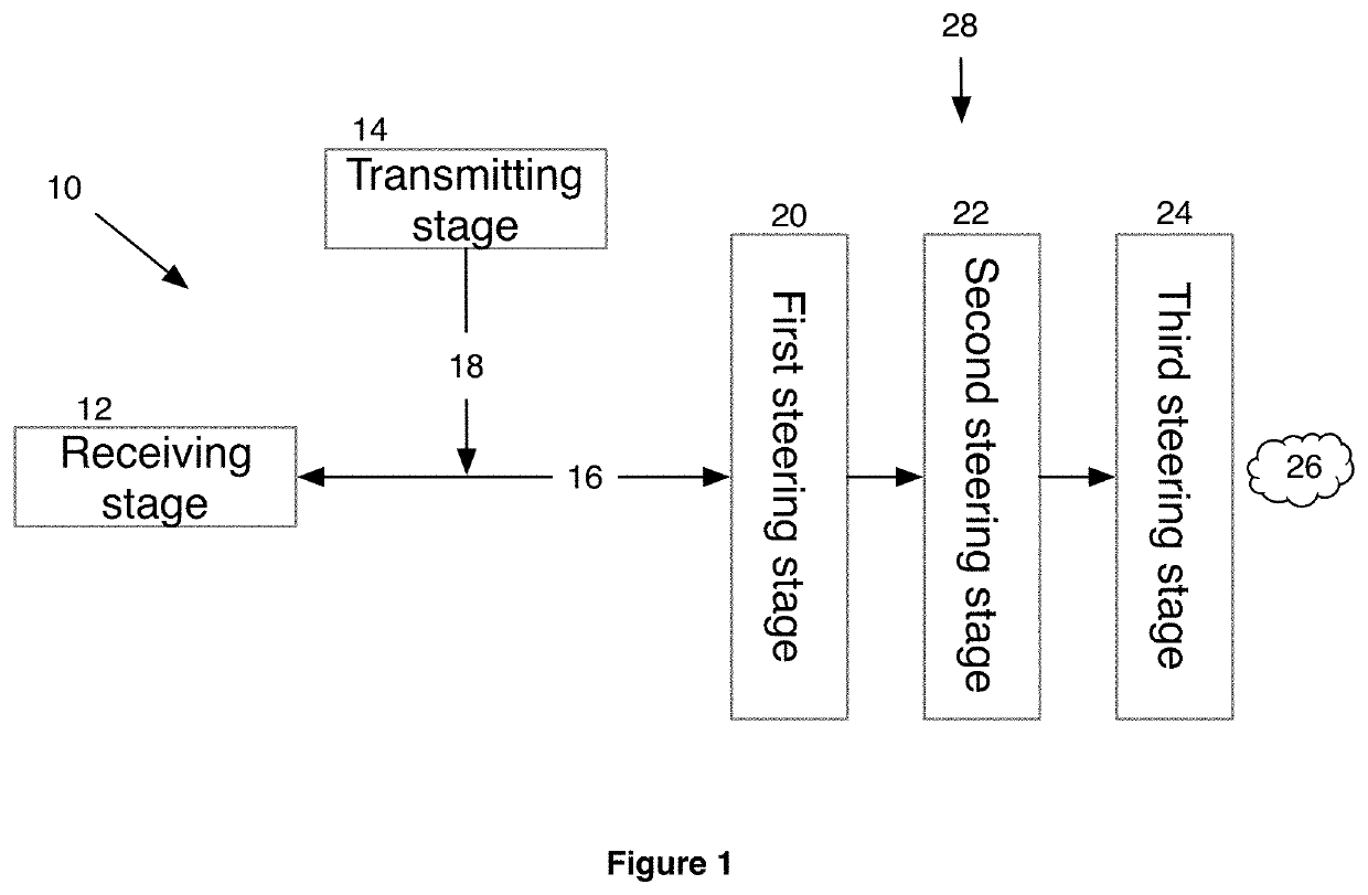
[0031]With reference to FIG. 1, a LIDAR apparatus 10 is shown which creates a point cloud depicting the scene 26. The LIDAR apparatus includes a transmitting stage 14, which includes a light source to illuminate the scene 26. Objects in the scene 26 will reflect or back scatter the projected light. The light returns are sensed by the receiving stage 12, where they are converted into electrical signals. The light returns convey distance information from objects in the scene 26 which can be measured on the basis of Time Of Flight (TOF) and Frequency-Modulated Continuous-Wave (FMCW), among others. A controller shown in FIG. 10 converts the electrical signals into a point cloud which is a set of data points in space that represent a 3D shape of the scene. Typically, but not always, each data point has a set of X, Y and Z coordinates.
[0032]The LIDAR apparatus 10 has a beam-steering engine 28, including multiple beam-steering stages. The LIDAR apparatus can be placed either at the back or...
PUM
 Abstract
Description
Claims
Application Information