
Electronic apparatus and controlling method thereof

a technology applied in the field of electronic equipment and control method, can solve the problems of not reflecting all the characteristics of inputs, generating various side effects (e.g., jagging or blurring) in images with text, and achieving the effect of improving the processing performance of input images

Active Publication Date: 2022-01-27
SAMSUNG ELECTRONICS CO LTD
View PDF0 Cites 5 Cited by
  • Summary
  • Abstract
  • Description
  • Claims
  • Application Information

AI Technical Summary

Benefits of technology

[0010]The present disclosure is provided in accordance with the above-described needs, and aims at providing an electronic apparatus for improving the processing performance of an input image by changing a processing method according to the type of the input image and controlling method thereof.
[0028]According to the various embodiments of the present disclosure, the electronic apparatus may identify the type of an input image using an artificial intelligence model, and improve processing performance of the input image by processing the input image using another artificial intelligence model corresponding to the identified type.

Problems solved by technology

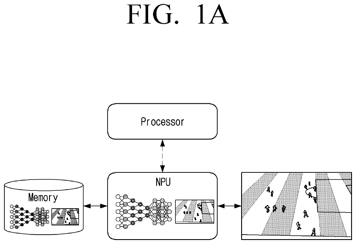
However, because of a limited computing resource, neural network algorithms may be optimized, but they do not reflect all the characteristics of inputs.
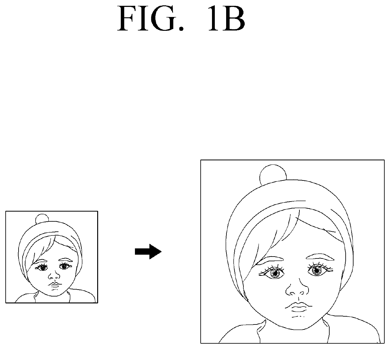
Specifically, if a single neural network model is applied to all inputs, desired results may not be produced for all inputs.
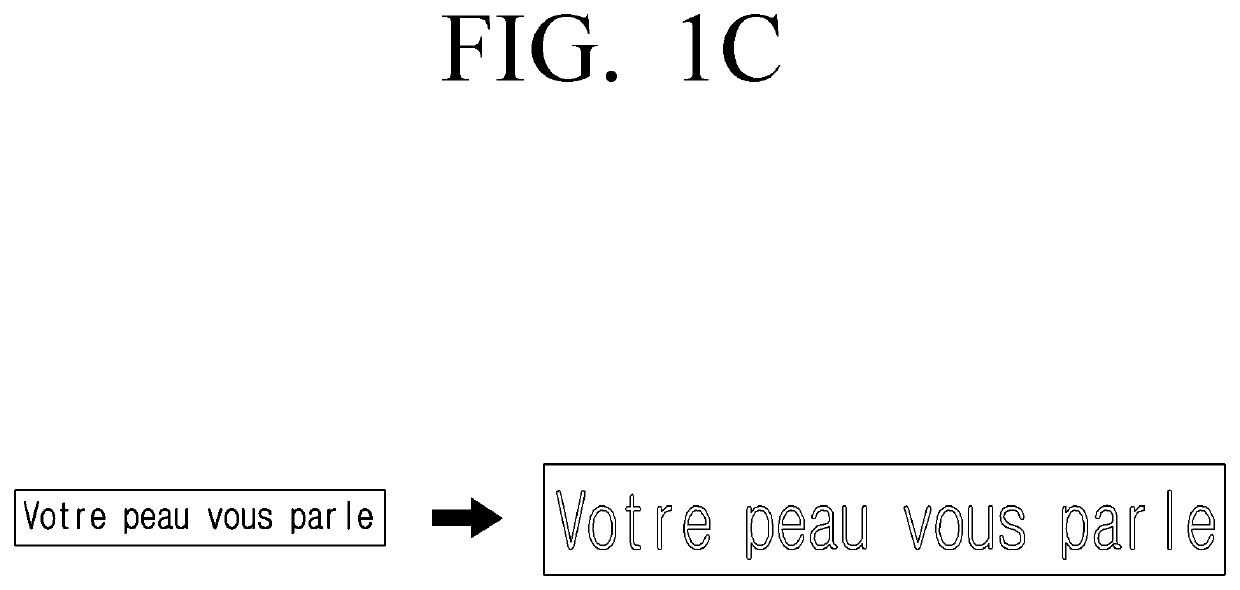
However, as illustrated in FIG. 1C, various side effects (e.g., jagging or blurring) may be generated in an image with text.
Due to such side effects, applying the same neural network model to all inputs is a problem in neural network technology.
However, in the former “sensing” case, the side effects of an image (e.g., after upscaling) should be sensed and eliminated, but the method is not appropriate in an environment where computing resources are limited.
In the latter “storing” case, there is a problem that there is no way of processing when there is no information in the input image.

Method used


Image

  • Electronic apparatus and controlling method thereof
  • Electronic apparatus and controlling method thereof
  • Electronic apparatus and controlling method thereof

Examples


Embodiment Construction

[0043]The exemplary embodiments of the present disclosure may be diversely modified. Accordingly, specific exemplary embodiments are illustrated in the drawings and are described in detail in the detailed description. However, it is to be understood that the present disclosure is not limited to a specific exemplary embodiment, but includes all modifications, equivalents, and substitutions without departing from the scope and spirit of the present disclosure. Also, well-known functions or constructions are not described in detail since they would obscure the disclosure with unnecessary detail.

[0044]Hereinafter, the present disclosure will be described in detail with reference to the accompanying drawings.

[0045]As for the terms used in the embodiments of the disclosure, general terms that are currently used widely were selected in consideration of the functions described in the disclosure. However, the terms may vary depending on the intention of those skilled in the art who work in t...


PUM


Abstract

An electronic apparatus may include a memory that stores first information regarding a plurality of first artificial intelligence models trained to perform image processing differently from each other and second information regarding a second artificial intelligence model trained to identify a type of an image by predicting a processing result of the image by each of the plurality of first artificial intelligence models. The electronic apparatus may further include a processor configured to identify a type of an input image by inputting the input image to the second artificial intelligence model stored in the memory, and process the input image by inputting the input image to one of the plurality of first intelligence models stored in the memory based on the identified type.

Description

CROSS-REFERENCE TO RELATED APPLICATIONS[0001]This application is a continuation of U.S. patent application Ser. No. 17 / 081,510, filed on Oct. 27, 2020, which claims priority from Korean Patent Application No. 10-2019-0150746, filed in the Korean Intellectual Property Office on Nov. 21, 2019, the disclosure of which is incorporated herein by reference.BACKGROUND1. Field[0002]Aspects of exemplary embodiments of the present disclosure relate to an electronic apparatus and a controlling method thereof and more particularly, to an electronic apparatus that processes an input image using an artificial intelligence model and a controlling method thereof.2. Description of the Related Art[0003]Recently, an electronic apparatus may perform image processing using a neural network technology which is represented by deep learning that has been developed rapidly. For example, the neural network technology may be applied to segmentation, super-resolution, HDR, etc.[0004]Such a neural network techn...

Claims


Application Information

Patent Timeline
Patent Type & Authority Applications(United States)
IPC IPC(8): G06K9/62G06N3/04G06N3/08G06T3/40G06T7/00
CPCG06K9/627G06K9/6256G06N3/0454G06N3/08G06T2207/30201G06T7/0002G06T2207/20081G06T2207/20084G06T2207/30168G06T3/40G06N3/063G06T3/4046G06N3/045G06T5/00G06T1/20G06T7/11G06T5/002G06V20/00G06F18/2413G06F18/214
Inventor TAI, YONGMINCHO, INSANGHWANG, CHANYOUNG
Owner SAMSUNG ELECTRONICS CO LTD
Learn More