
Proportional valve

Active Publication Date: 2022-02-03
ETO MAGNETIC GMBH
View PDF0 Cites 0 Cited by
  • Summary
  • Abstract
  • Description
  • Claims
  • Application Information

AI Technical Summary

Benefits of technology

The present invention is an improved electromagnetically and pilot-operated proportional valve design that improves bearing and guiding properties in the valve housing. It allows for a realization of a valve slide that can be optimized for required pressure engagement surfaces and can be pilot-controlled on both axial sides. The invention eliminates bearing redundancy and minimizes the risk of malfunctions by providing play in the bearing assemblies and ring-shaped sealing means to limit pilot fluid entry space. The invention is simple in design and mechanics, reliable, and suitable for high-pressure fluid control applications in automotive or vehicle context.

Problems solved by technology

However, such a direct control is often impractical or is not technically feasible, in particular in connection with high pressures in the useful fluid, the valve slide (valve slide unit) of such a way valve thus being operated by means of a so-called pilot control and therefore indirectly by the effect of the electromagnetic actuator assembly.
Such a bearing of a valve slide unit by means of conventional means would lead to bearing redundancies because of the (sliding) bearing to be provided at both axial ends of the valve slide unit and at the radial circumference in relation to a surrounding valve housing, wherein said bearing redundancies either severely limit the options of a control or dimensioning of such a unit or even make it impossible to realize certain design options (such as a bidirectionally switchable pilot-control fluid guiding through the valve slide unit).

Method used


Image

  • Proportional valve

Examples


Embodiment Construction

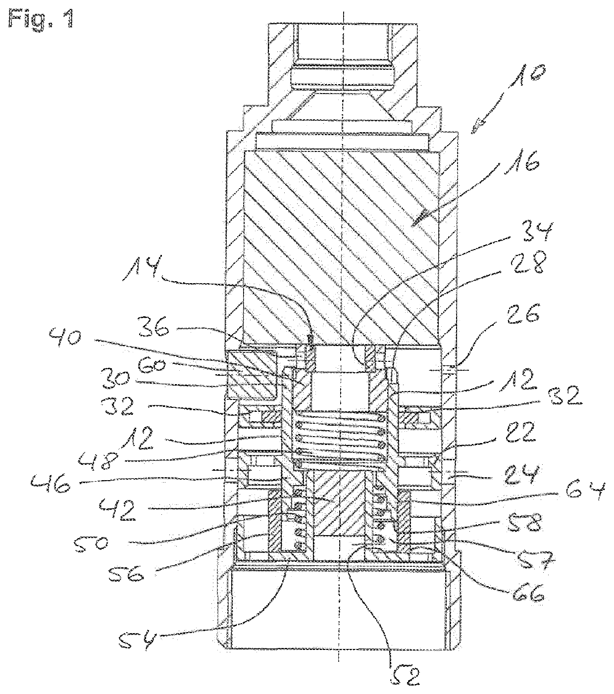
[0027]A valve slide unit 12 is mounted in a valve housing 10 of the proportional valve so as to be movable in an axial direction; the axial direction corresponds to the vertical direction in the drawing layer of FIG. 1 and in this respect to an actuator movement direction of a (radially symmetrical) armature slide unit (armature slide) 14 of an electromagnetically operated actuator assembly 16 which is provided in the upper end at the end in valve housing 10. In a manner known per se, armature slide unit 14 is axially moved against a restoring force of spring means of actuator assembly 16 in response to an energization of stationary coil means (upwards in the drawing layer and towards stationary core means of actuator assembly 16 not shown in detail in the case at hand).

[0028]Electromagnetic actuator assembly 16 is used for the realization of an electromagnetically operated pilot valve by means of which valve slide unit 12 is piloted in order to drive it. More precisely, a pilot flu...


PUM


Abstract

An electromagnetic and pilot-operated proportional valve with a valve slide unit (12) mounted in a valve housing (10) so as to be movable along an axial direction, which unit can be driven by an electromagnetic actuator assembly (16) provided at one axial end for the pilot-operated opening of a useful fluid inlet and / or outlet (24) of the valve housing as a response to energisation of a stationary coil (20) of the actuator assembly and interacts with mechanical force storage means (48, 50), more particularly is held in an unenergised stable axial position in the valve housing by said means, wherein the valve slide unit having a closure section (22) extending radially from one body section (30) of the valve slide unit (12) for sealing interaction with the useful fluid inlet or outlet (24) formed on a circumferential inner wall of the housing (10) interacts axially at one end, by means of the preferably cylindrical and / or coaxially extending body section (22), with a stationary guide section (40) of the valve housing to form an axial sliding bearing (62) and, at the other end, is mounted with radial play (56), wherein preferably ring-shaped sealing means (32) seal a circumferential section of the body section with radial play to the circumferential inner wall of the valve housing.

Description

BACKGROUND OF THE INVENTION[0001]The present invention relates to an electromagnetically and pilot-operated proportional valve.[0002]Such a device is generally known in the form of conventional electromagnet valves, such as those developed and produced by the applicant, for example, and usually has a valve slide which is operated by an electromagnetic actuator assembly, the valve slide then opening or closing a fluid flow path to be (proportionally) controlled by the valve in the provided manner. In particular, it is known to dispose openings to be opened or to be closed in an accordingly controlled manner in a circumferential area of a valve housing (which is usually oblong in an axial direction), a valve slide guided on the inside of the valve housing then interacting with the openings and (partially or entirely) opening the inlet or outlet for the useful fluid according to its position (which is electromagnetically influenced by the actuator assembly).[0003]In said generic and kn...

Claims


Application Information

Patent Timeline
IPC IPC(8): F16K3/316F16K27/04F16K31/06F16K31/122F16K31/124F16K31/42
CPCF16K3/316F16K27/048F16K31/0668F16F9/465F16K31/124F16K31/42F16K31/1221F16F9/464F16F9/46
Inventor BÜRSSNER, JÖRGVINCON, PETER
Owner ETO MAGNETIC GMBH
Learn More