
Thermostatic mixing valve

a technology of mixing valve and thermostat, which is applied in the direction of multiple way valve, valve details, instruments, etc., can solve the problems of difficult implementation, expensive, time-consuming, etc., and achieve the effect of improving the known thermostatic mixing valve, simple and rapid way

Inactive Publication Date: 2022-02-03
BOME
View PDF0 Cites 0 Cited by
  • Summary
  • Abstract
  • Description
  • Claims
  • Application Information

AI Technical Summary

Benefits of technology

This patent is for a better thermostatic mixing valve. It can calibrate fluid temperature quickly and easily, allowing for inspection, maintenance, or replacement of valve parts without having to repeat the calibration process. The valve is also simple and inexpensive to manufacture. It allows for direct access to the inner parts and easy assembly and disassembly.

Problems solved by technology

First of all, due to the rather complex structure of the components forming the valve, it is not possible to have direct access to all the inner components of the valve. Inspection and / or maintenance and / or component replacement and / or valve cleaning operations are time-consuming, expensive and may be hard, if not impossible, to be implemented when the space available for manoeuvres is limited and poorly accessible to make it possible to extract all the inner components of the valve.
Another drawback is that, after performing the maintenance operation, the operator has to carry out again a calibration / setting of the temperature of the fluid exiting the valve.
This involves an additional waste of time to calibrate again the temperature of the flow exiting the mixing valve.

Method used


Image

  • Thermostatic mixing valve
  • Thermostatic mixing valve
  • Thermostatic mixing valve

Examples


Embodiment Construction

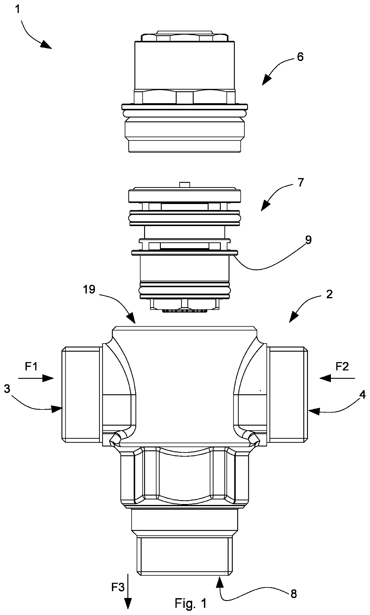
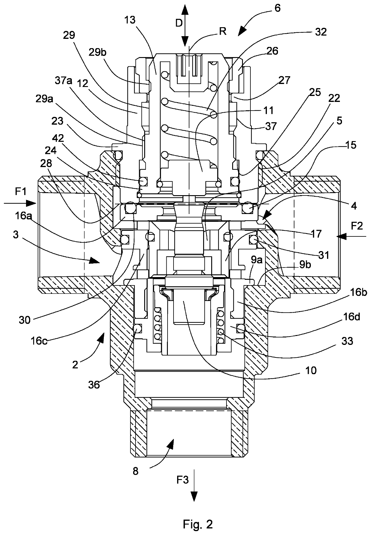
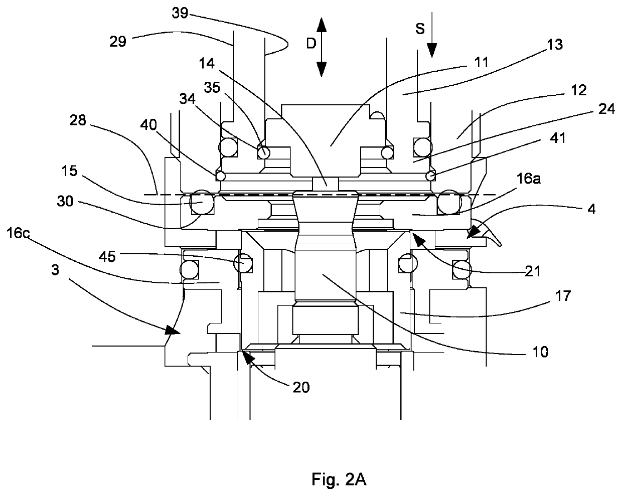
[0028]With reference to the enclosed Figures, it is shown a thermostatic mixing valve 1 adapted to be assembled in a building heating circuit, in particular in sanitary systems, and having the function to maintain the temperature of the exiting mixed water, constant, at a desired value. The thermostatic mixing valve 1 may be assembled upstream of a system for supplying a fluid to one or more users.

[0029]As will be clear in greater detail from the following description, the thermostatic mixing valve 1 is configured to keep the temperature of the mixed water at a desired value based on a calibration or setting operation carried out on the components of the valve. Furthermore, the thermostatic mixing valve 1, or thermostatic mixing valve unit, allows to self-regulate the temperature as the water supply conditions, i.e., the temperatures of the entering water flows, vary.

[0030]The thermostatic mixing valve 1 includes a valve body 2 provided with an inner cavity 18.

[0031]The valve body 2...


PUM


Abstract

Thermostatic mixing valve including a valve body provided with an inner cavity, a first inlet for a first flow of water into the cavity, a second inlet for a second flow) of water into the cavity, and an outlet for a third flow of mixed water exiting the cavity, a mixing device shaped to be placed in fluid connection with the first inlet, the second inlet and the outlet, and to define a mixing chamber for the first and second flow, the mixing device being internally provided with a thermostatic actuating element that is movable along an operating direction, and a temperature adjusting device provided with a housing and with a positioning element that is slidable with respect to the housing, and configured for adopting, by adjustment, a set position with respect to the housing, and for imposing on the thermostatic actuating element a calibration position along the operating direction corresponding to a desired mixing temperature.The mixing device includes a plug member connected to the thermostatic actuating element and drivable along the operating direction through the effect of a contracting / dilating movement of the thermostatic actuating element for controlling the entry of first flow and second flow into the mixing chamber so as to maintain the third flow at the desired mixing temperature. The mixing device is removably housed in the cavity by coupling at least one abutting portion of the mixing device with at least one abutting surface of the cavity. On the valve body, in a position opposite to the outlet, an opening end is provided to enable the mixing device to be inserted into the cavity; the temperature adjusting device, in a coupling configuration is shaped for coupling with the mixing device along a coupling surface and for closing the opening end; the positioning element is configured for remaining in the set position with respect to the housing also in a decoupling configuration of the temperature adjusting device from the mixing device and from the valve body, so as to preserve, once the temperature adjusting device, the mixing device and the valve body have been subsequently recoupled, the calibration position corresponding to the desired mixing temperature.

Description

[0001]The invention relates to a thermostatic mixing valve.[0002]In particular, the invention relates to a thermostatic mixing valve arranged to adjust a temperature of a fluid flow, in particular water, circulating in a supply system to one or more users.BACKGROUND OF THE INVENTION[0003]There are known thermostatic mixing valves used in hot water supply systems for sanitary use, having the function to maintain constant, at a set value, the temperature of the mixed water sent to the user, as conditions regarding temperature, pressure, cold and hot water flow rate entering the valve, change. The thermostatic mixing valve includes a valve body provided with a first inlet for hot water, a second inlet for cold water and an outlet for the mixed water. The valve includes a hollow cartridge element, mounted inside the valve body and provided with walls in fluid communication with the inlets and the outlet, and defining, in the valve body, a mixing chamber in which the hot fluid is mixed w...

Claims


Application Information

Patent Timeline
Patent Type & Authority Applications(United States)
IPC IPC(8): F16K31/00F16K11/07
CPCF16K31/002F16K11/0704G05D23/1346
Inventor MEDINA, CARLO
Owner BOME
Learn More