Cyclone separation device

Active Publication Date: 2022-02-10
KONINKLJIJKE PHILIPS NV
View PDF0 Cites 0 Cited by
  • Summary
  • Abstract
  • Description
  • Claims
  • Application Information

AI Technical Summary

Benefits of technology

[0005]An aspect of the invention provides a cyclone separation device that comprises a cyclone chamber for separating dirt from incoming air, a dirt collecting chamber arranged adjacent to the cyclone chamber for collecting dirt particles separated from air, and a dirt duct between the cyclone chamber and the dirt collecting chamber for allowing dirt particles to exit the cyclone chamber into the dirt collecting chamber. To reduce the generation of noise-generating air vortices, the dirt duct has an edge protruding into a direction at an angle to the dirt duct at an exit ridge of the cyclone chamber that is first encountered by the air rotating in the cyclone chamber. Preferably, the edge is formed by a tangential extension of a wall of the cyclone chamber. Preferably, a width of the edge is at least 5 mm, and more preferably at least 8 mm, and even more preferably 12 mm. A vacuum cleaner advantageously comprises such a cyclone separation device.
[0006]Embodiments of the invention provide a solution having a special new shaped dirt outlet geometry from the cyclone chamber towards the dust bucket that doe

Problems solved by technology

Vortex shedding at the first exit ridge of the dirt exit is limited.
As a result of this need to make a turn of at least 90° if the air wished to

Method used


Image

  • Cyclone separation device

Examples


Embodiment Construction

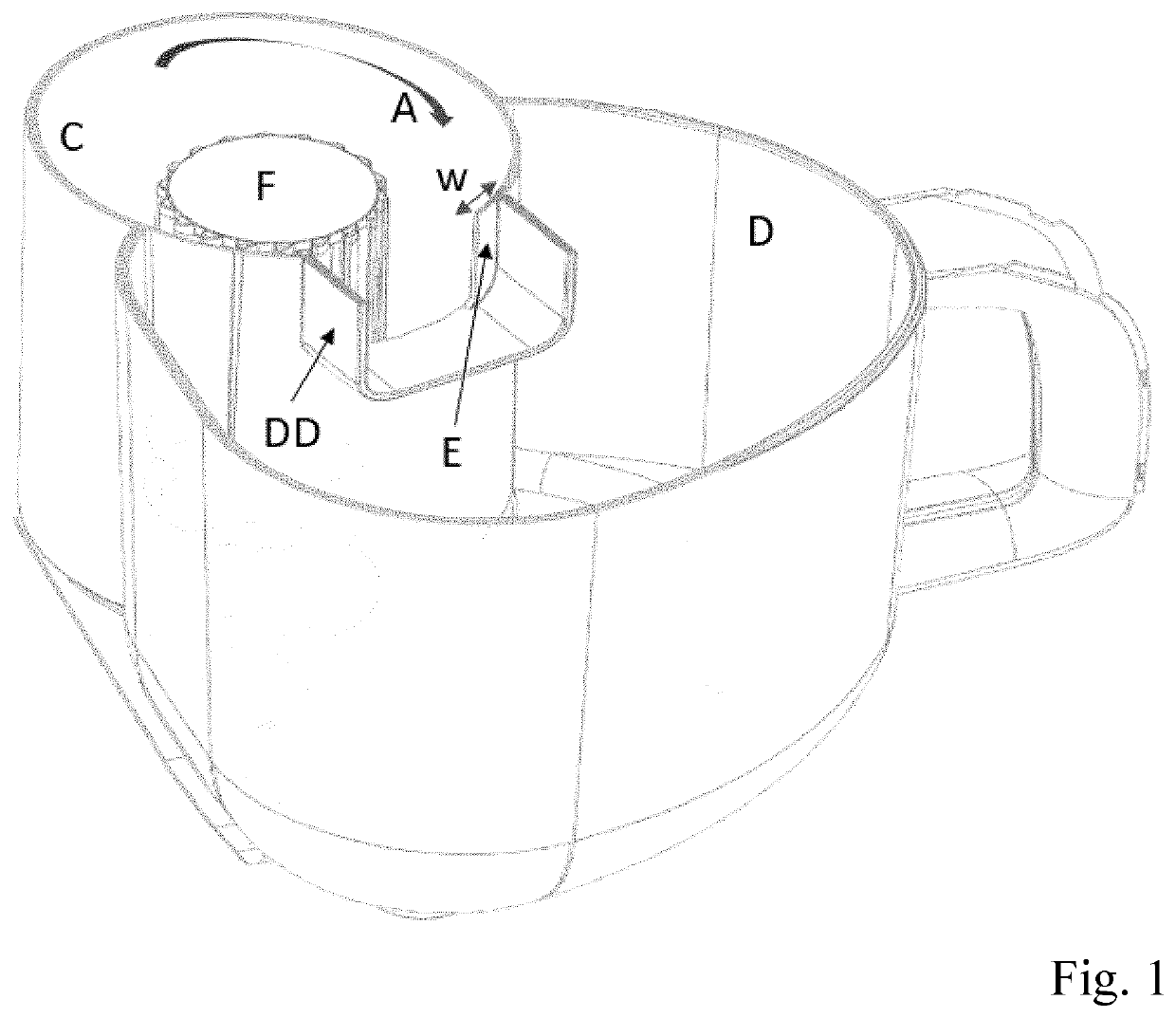
[0009]FIG. 1 shows an embodiment of a cyclone separation device in accordance with the present invention. Like in US2014373307, the cyclone separation device has a cyclone chamber C, a dirt collecting chamber D arranged adjacent to the cyclone chamber C for collecting dirt particles separated from air, a dirt duct DD between the cyclone chamber C and the dirt collecting chamber D for allowing dirt particles to pass from the cyclone chamber C towards the dirt collecting chamber D. As shown in the FIGURE, the dirt duct DD may generally extend in a longitudinal direction that is a radial to the cyclone chamber C. The cyclone chamber C may have a cylinder-shaped vortex finder F having a plurality of stationary vanes at its outer circumference, or some other air exit for allowing air with a reduced amount of dirt to leave the cyclone chamber C. Air A is rotating clockwise in the cyclone chamber C.

[0010]In accordance with a feature of the present invention, an edge E protrudes into the di...


PUM


Abstract

A cyclone separation device includes a cyclone chamber for separating dirt from incoming air, a dirt collecting chamber arranged adjacent to the cyclone chamber for collecting dirt particles separated from air, and a dirt duct between the cyclone chamber and the dirt collecting chamber for allowing dirt particles to exit the cyclone chamber into the dirt collecting chamber. To reduce the generation of noise-generating air vortices, the dirt duct has an edge protruding into a direction at an angle to the dirt duct at an exit ridge of the cyclone chamber that is first encountered by the air rotating in the cyclone chamber. Preferably, the edge is formed by a tangential extension of a wall of the cyclone chamber. A vacuum cleaner advantageously includes such a cyclone separation device.

Description

FIELD OF THE INVENTION[0001]The invention relates to a cyclone separation device, and to a vacuum cleaner comprising such a cyclone separation device.BACKGROUND OF THE INVENTION[0002]A cyclone technology can be used in a bag-less vacuum cleaner to separate dirt particles from the dirty air flowing through the appliance. The dirt particles are collected in a special dust bucket after separation from the main air flow. Cyclone separators allow vacuum cleaners to maintain a constant vacuuming performance. The air enters the cyclone chamber at the bottom and will flow cyclonic due to the geometry. Dirt particles are pushed outwards by the generated centrifugal forces and follow a spiral path upwards towards the exit of the cyclone chamber into the dust bucket. The air flow in the cyclone chamber will exit the system at the center. The air inside the cyclone chamber is spinning fast and passes the exit ridges at the top. Due to the large gap in combination with the ridges, vortices are g...

Claims


Application Information

Patent Timeline
IPC IPC(8): B04C5/185B04C5/103B04C5/13A47L9/16
CPCB04C5/185B04C5/103B04C5/13B04C2005/136A47L9/1658A47L9/1683A47L9/1608A47L9/0081B04C5/14
Inventor VAN DEN BOSCH, MICHAELVAN DER KOOI, JOHANNES TSEARDELZINGA, MARK
Owner KONINKLJIJKE PHILIPS NV
Why Eureka
Try Eureka