Control system with cascade driving circuits and related driving method

a control system and driving circuit technology, applied in static storage, digital storage, instruments, etc., can solve the problems of time delay on signal flow, signal reception time difference between different chips, and single chip may not be enough to deal with the enormous amount of display data

Active Publication Date: 2022-02-10
NOVATEK MICROELECTRONICS CORP
View PDF0 Cites 2 Cited by
  • Summary
  • Abstract
  • Description
  • Claims
  • Application Information

AI Technical Summary

Benefits of technology

[0005]It is therefore an objective of the present invention to provide a control system composed of cascade chips and a related driving method to perform synchronization between the chips.

Problems solved by technology

Therefore, due to the high resolution of the modern display system, a single chip may not be enough to deal with the tremendous quantity of display data, and the multi-chip system may be more feasible.
Thus, there is a time delay on the signal flow from one chip to another, and a time difference of signal reception arises between different chips.
Thus, how to synchronize the operations of the chips in a multi-chip system has become an important issue in this art.

Method used


Image

  • Control system with cascade driving circuits and related driving method
  • Control system with cascade driving circuits and related driving method
  • Control system with cascade driving circuits and related driving method

Examples


Embodiment Construction

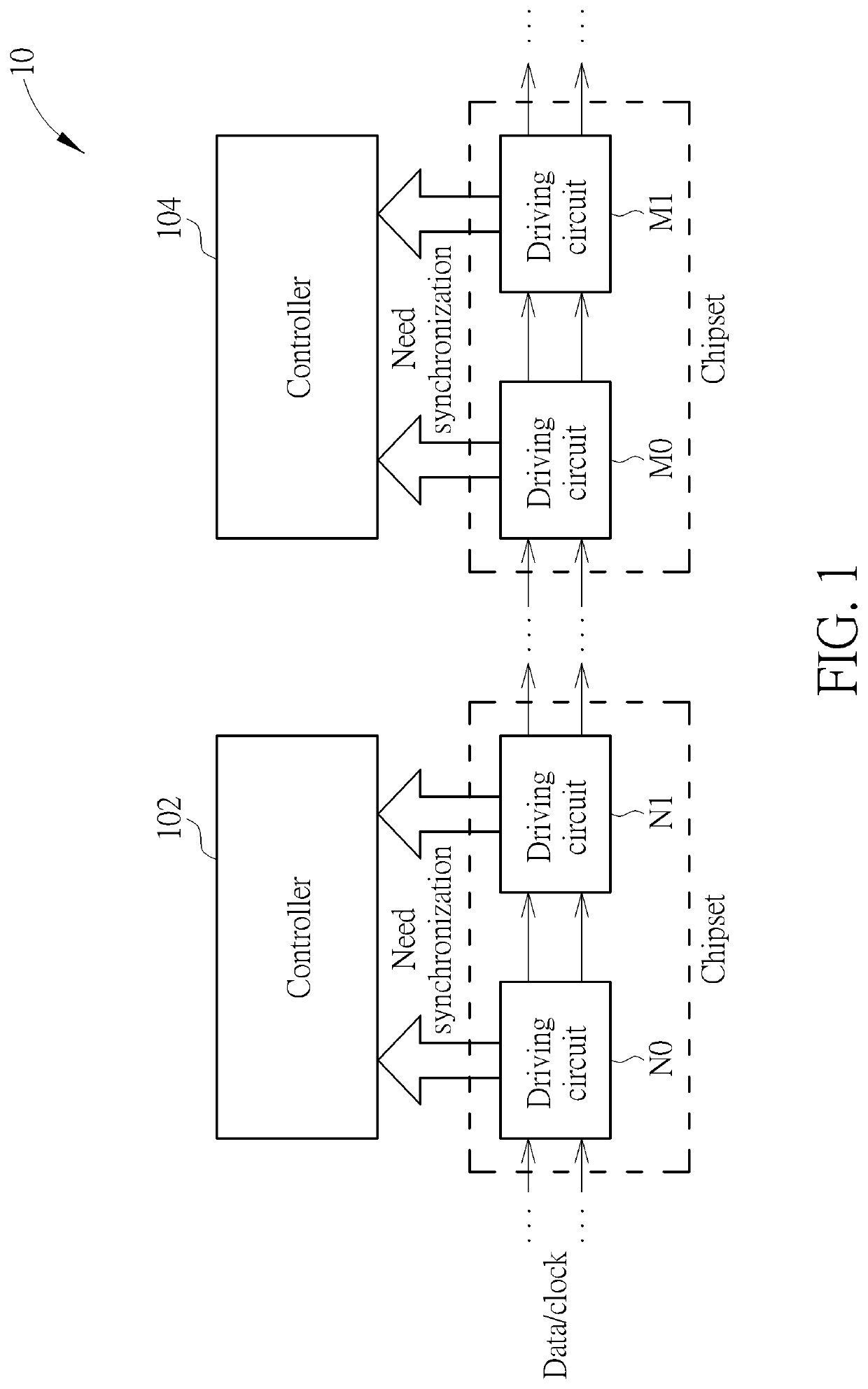
[0018]Please refer to FIG. 1, which is a schematic diagram of a control system 10. As shown in FIG. 1, the control system 10 includes controllers 102 and 104, and driving circuits N0, N1, M0 and M1 for controlling the controllers 102 and 104, respectively. In detail, the driving circuits N0 and N1 are used for driving the controller 102 and the driving circuits M0 and M1 are used for driving the controller 104. Each driving circuit may be an integrated circuit (IC) implemented in a chip. Therefore, the driving circuits N0 and N1 may be a chipset configured to control the controller 102, and the driving circuits M0 and M1 may be a chipset configured to control the controller 104. The controllers 102 and 104 may broadly refer to any type of control circuit being served as a load receiving controls from the driving circuits and / or providing a control function.

[0019]In detail, in the control system 10, the driving circuits are coupled in series. A signal source may provide a data or clo...


PUM


Abstract

A control system includes a plurality of driving circuits coupled in series, which includes a first driving circuit and a second driving circuit. The first driving circuit includes a first receiver, a first transmitter and a replica receiver. The first transmitter is coupled to the first receiver, and the replica receiver is coupled to an output terminal of the first transmitter. The second driving circuit, coupled to the first driving circuit, includes a second receiver and a second transmitter. The second receiver is coupled to the first transmitter, and the second transmitter is coupled to the second receiver.

Description

Cross Reference To Related Applications[0001]This application claims the benefit of U.S. Provisional Application No. 63 / 061,811, filed on Aug. 6, 2020, the contents of which are incorporated herein by reference.BACKGROUND OF THE INVENTION1. Field of the Invention[0002]The present invention relates to a control system with cascade driving circuits and a related driving method, and more particularly, to a synchronization technique performed on a control system with cascade driving circuits and a related synchronization method.2. Description of the Prior Art[0003]As the data quantity to be processed in a control system increases and increases, a multi-chip system may be required. The deployment of multiple chips allows a tremendous amount of data to be processed successfully. In a multi-chip system, the chips may be coupled in series as a cascade structure, where each chip may receive signals from the previous one and forward the signals to the next one. The transmitted signals maybe r...

Claims


Application Information

Patent Timeline
Patent Type & Authority Applications(United States)
IPC IPC(8): G11C19/28G09G3/20
CPCG11C19/28G09G2310/08G09G2310/0286G09G3/20G09G3/32G09G3/36G09G3/2077
Inventor YEH, CHE-WEILIANG, KEKO-CHUNWANG, YU-HSIANGFANG, YONG-RENLIU, YI-CHUANTSAI, YI-YANGFANG, PO-HSIANG
Owner NOVATEK MICROELECTRONICS CORP
Why Eureka
Try Eureka