Transmitter apparatus and transmission method for a wireless power transmission system providing improved wireless power transmission efficiency

a transmission method and transmission method technology, applied in electrical equipment, radio transmission, antennas, etc., can solve problems such as difficult to maximize wireless power transmission efficiency, and achieve the effect of maximum transmission efficiency

Active Publication Date: 2022-02-10
IND ACADEMIC CORP FOUND YONSEI UNIV
View PDF0 Cites 0 Cited by
  • Summary
  • Abstract
  • Description
  • Claims
  • Application Information

AI Technical Summary

Benefits of technology

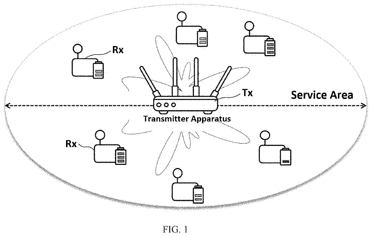
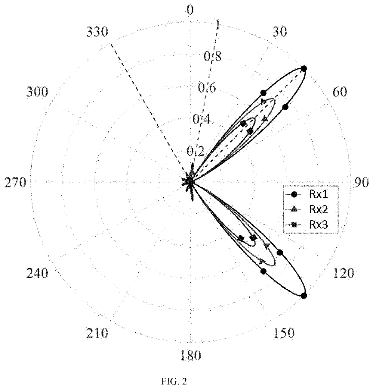
">[0029]Thus, a transmitter apparatus and a transmission method for a wireless power transmission system according to an embodiment of the present disclosure can provide maximum transmission efficiency in transmitting wireless power signals with multi-lobe beamforming towards multiple receiver apparatuses from a transmitter apparatuses having a multiple number of antennas by adjusting the beamforming vector, which is for adjusting the gains and phases of the signals supplied to the multiple antennas, and the frequency vector, which is for adjusting the frequencies of the signals supplied to the multiple antennas, according to the positions of the multiple receiver apparatuses waiting to receive the wireless power signal

Problems solved by technology

However, in an environment where power is required by multiple receiver devices, it may not be easy to maximize wireless power transmission efficiency.

Method used


Image

  • Transmitter apparatus and transmission method for a wireless power transmission system providing improved wireless power transmission efficiency
  • Transmitter apparatus and transmission method for a wireless power transmission system providing improved wireless power transmission efficiency
  • Transmitter apparatus and transmission method for a wireless power transmission system providing improved wireless power transmission efficiency

Examples


Embodiment Construction

[0037]To sufficiently understand the present disclosure, the advantages provided by operation of the present disclosure, and the objectives achieved by practice of the present disclosure, it may be necessary to reference the appended drawings, which illustrate preferred embodiments of the present disclosure, as well as the descriptions associated with the appended drawings.

[0038]Below, a detailed description of the present disclosure is provided, through a detailed description of preferred embodiments that reference the accompanying drawings. However, the present disclosure can be implemented in many different forms and is not limited to the embodiments described herein. For a clear description of the present disclosure, certain portions that are not of great relevance to the descriptions have been omitted, and like reference numerals have been assigned to like components in the drawings.

[0039]Throughout the specification, mention of a part “including” a certain component does not p...


PUM


Abstract

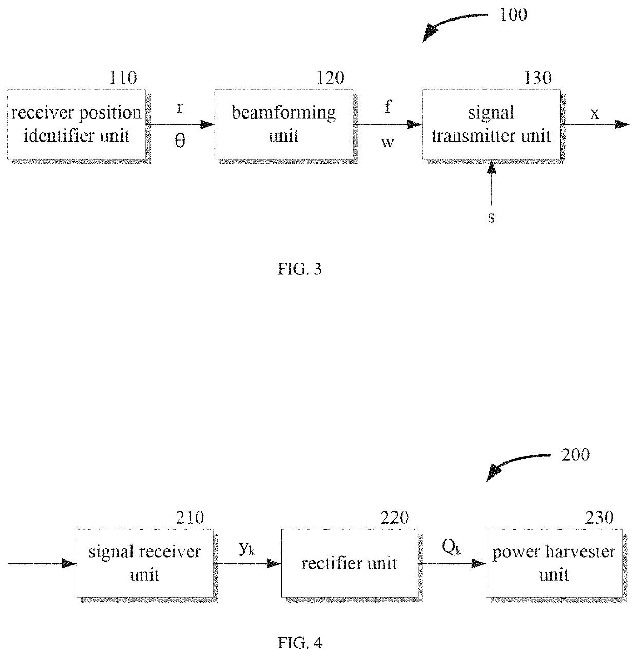
A wireless power transmission system includes a receiver position identifier unit configured to determine the positions of receiver apparatuses; a signal transmitter unit comprising antennas arrayed in a pre-designated pattern and configured to radiate wireless power signals by forming a beam in a pattern corresponding to signals supplied respectively to the antennas; and a beamforming unit configured to improve a wireless power transmission efficiency by temporarily setting a frequency vector, which is for designating frequencies of the signals supplied to the antennas, and a beamforming vector, which is for designating phases and gains of the signals, based on the positions of the receiver apparatuses and alternatingly iteratively estimating the other vector to enhance power transmission efficiency such that a multi-lobe beam pattern radiated simultaneously in the directions of the receiver apparatuses is formed in the antennas.

Description

CROSS-REFERENCE TO RELATED APPLICATIONS[0001]This application claims priority to Korean Patent Application No. 10-2020-0097321, filed with the Korean Intellectual Property Office on Aug. 4, 2020, the disclosure of which is incorporated herein by reference in its entirety.BACKGROUND1. Technical Field[0002]The present disclosure relates to a transmitter apparatus and a transmission method for a wireless power transmission system, more particularly to a transmitter apparatus and transmission method for a wireless power transmission system that can improve the efficiency of the wireless power transmission in an environment for transmitting wireless power signals to multiple receiver apparatuses.2. Description of the Related Art[0003]With recent advances in wireless network technology, there is a rapid growth in the numbers of IoT (Internet of Things) devices. In order to effectively manage a large-scale wireless network, there is a need for a system capable of supplying power to the IoT...

Claims


Application Information

Patent Timeline
Patent Type & Authority Applications(United States)
IPC IPC(8): H02J50/90H02J50/40H02J50/80H02J50/00H02J50/20
CPCH02J50/90H02J50/402H02J50/20H02J50/001H02J50/80H02J50/40H02J50/23H04B7/0617H04B7/0408H01Q3/26
Inventor LEE, CHUNG YONGIM, CHAE HUNJUNG, SANG WON
Owner IND ACADEMIC CORP FOUND YONSEI UNIV
Why Eureka
Try Eureka